Kia Sportage: Components and Components Location | Panoramaroof Switch | Panoramaroof Motor
Component Location
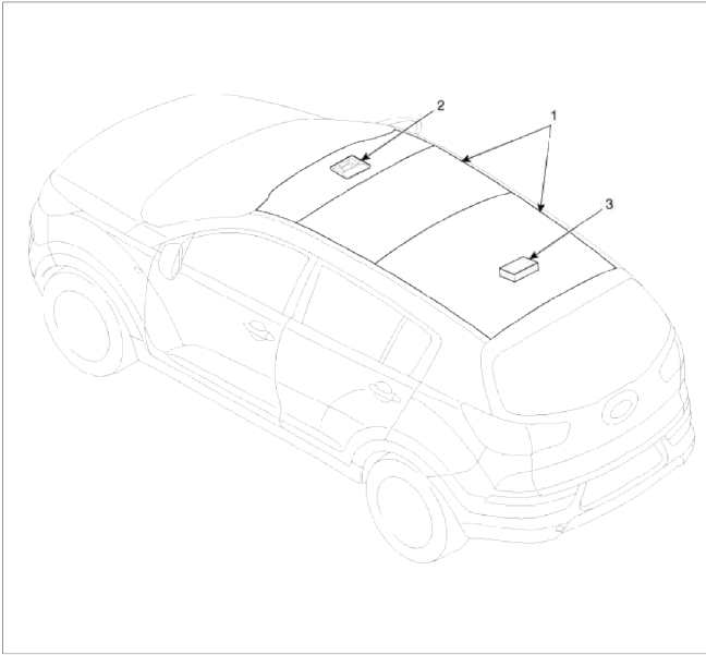
- Panoramaroof
- Panoramaroof switch
- Panoramaroof motor & controller
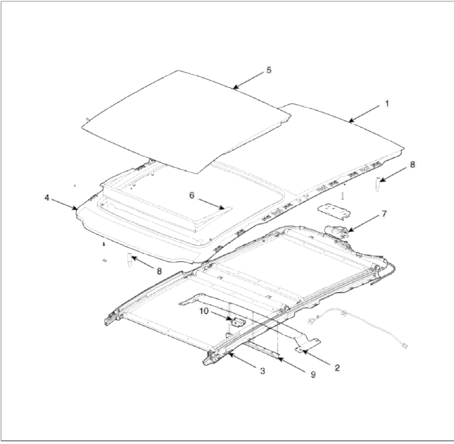
Components
-
Panoramaroof frame assembly
-
Panoramaroof impact cross member assembly
-
Panoramaroof mechanism assembly
-
Panoramaroof front glass panel assembly
-
Panoramaroof moving glass panel assembly
-
Panoramaroof deflector assembly
-
Panoramaroof motor assembly
-
Panoramaroof center device
-
Impact bracket
-
Warning controller assembly
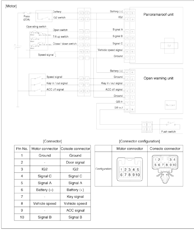
Schematic Diagrams
Circuit Diagram (1)
[Motor]
Circuit Diagram (2)
[Panoramaroof Switch]
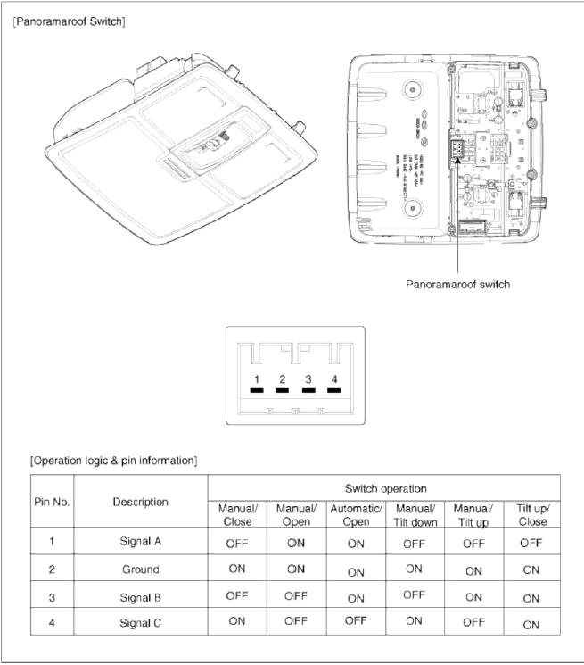
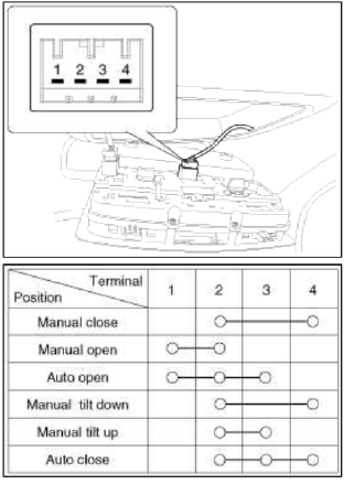
Panoramaroof Switch
Repair procedures
Inspection
1. Disconnect the negative (-) battery terminal.
2. Remove the overhead console lamp assembly.
(Refer to the BD group - "Roof trim")
3. Check for continuity between the terminals. If the continuity is not as specified, replace the sunroof switch.
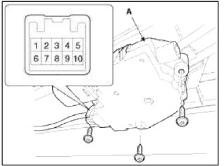
Panoramaroof Motor
Repair procedures
Replacement
1. Disconnect the negative (-) battery terminal.
2. Remove the roof trim.
(Refer to the BD group - "Roof trim")
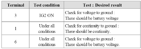
3. Remove the panoramaroof motor (A) after disconnecting the connector (10 Pin).
4. Ground the terminals as below table, and check that the panoramaroof runt operates as below table.
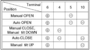
5. Make these input tests at the motor connector of panoramaroof harness.
If any test indicates a problem, find and correct the cause, then recheck the system.
If all the input tests prove OK, the sunroof motor must be faulty; replace it.
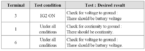
6. Make these input tests at the console connector of panoramaroof harness.
If any test indicates a problem, find and correct the cause, then recheck the system.
If all the input tests prove OK, the sunroof motor must be faulty; replace it.
Resetting The Panoramaroof
Whenever the vehicle battery is disconnected or discharged, or you use the emergency handle to operate the Panoramaroof, you have to reset your Panoramaroof system as follows:
1. Turn the ignition key to the ON position and then close the panoramaroof completely.
2. Release the panoramaroof control lever.
3. Press and hold the CLOSE button for more than 10 seconds until the sunroof has moved slightly.
4. Release the panoramaroof control lever.
5. Press and hold the CLOSE button once again until the sunroof do as follows;
- Tilt → Slide Open → Slide Close Then release the lever.
6. Reset procedure of panoramaroof system is finished.
Protecting The Overheated Motor
In order to protect the overheated Panoramaroof motor by continuous motor operation, the Panoramaroof ECU controls the Run-time and Cool-time of motor as followings;
1. The Panoramaroof ECU detects the Run-time of motor.
2. Motor can be operated continuously for the 1st Run-time (120 +- l0sec.).
3. Motor which is operated continuously stops operating after the 1st Run-time (120 +- l0sec.).
4. And then Motor is not operated for the 1st Cool-time (18 +- 2sec.).
5. Motor is operated for the 2nd Run-time (10 +- 2sec.) at the continued motor operation after 1st Cool-time (18 +- 2 sec.)
6. Motor which is operated continuously stops operating after the 2nd Run-time (10 +- 2sec.)
7. Motor is not operated for the 2nd Cool-time (18 +- 2sec.).
8. Motor repeats the 2nd Run-time and 2nd Cool-tune at the continued motor operation.
- In case that motor is not operated continuously, the Run-time which is limited for protecting the overheated motor is increased.
- The Run-Time of motor is initialized to "0" if the battery or fuse is reconnected after being disconnected, discharged or blown.
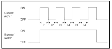
T1 : 120 +- 10 sec., T2 : 18 +- 2 sec., T3 : 10 +- 2 sec., T4 : 18 +- 2 sec.
READ NEXT:
SEE MORE:
 Smart ISG features
Early Engine Restart
If the engine was stopped automatically
by ISG, Early Engine Restart can automatically restart the engine from ISG
without driver action when the vehicle
ahead pulls away and the front view
camera detects the preceding vehicle's
movement.
If the engine restarts au
Navigation-based Smart Cruise Control operation
Operating conditions
Navigation-based Smart Cruise Control
is ready to operate if all of the following
conditions are satisfied:
Smart Cruise Control is operating
Driving on main roads of highways (or
motorways)
WARNING
Navigation-based Smart Cruise Control
(NSCC) is a supplemental s
Content
- Home
- Kia Sportage - Fifth generation (NQ5) - (2022-2026) - Owner's Manual
- Kia Sportage - Second generation (JEKM) (2005-2015) - Body Workshop Manual
- Kia Sportage Third generation (SL) - (2011-2016) - Service and Repair Manual
- Sitemap
- Top articles
