Kia Sportage: AUTO STOP

- Timer
AUTO STOP display shows the elapsed time of engine stop by Idle Stop and Go (ISG) system.
If the ISG does not operate, the reason for the non-operation is displayed. (if equipped) For more details, refer to "Idle Stop and Go (ISG) system"
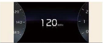
Digital speedometer
This digital speedometer display shows the speed of the vehicle.
Service mode
This mode reminds you of scheduled maintenance information.
- Service Interval
- Service interval schedule
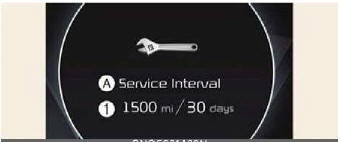
Service Interval
It calculates and displays when you need a scheduled maintenance service (mileage or days).
If the remaining mileage or time reaches 900 miles (1,500 km) or 30 days, "Service interval" message is displayed for several seconds each time you set the ignition switch or ENGINE START/STOP Button to the ON position.
Service required
If you do not have your vehicle serviced according to the already input service interval, "Service required" message is displayed for several seconds each time you set the ignition switch or ENGINE START/STOP Button to the ON position.
To reset the service interval to the mileage and days you input before: Select 'Vehicle settings Interval Reset'.
NOTICE
If any of the following conditions occur, the mileage and days may be incorrect.
- The battery cable is disconnected.
- The battery is discharged.
READ NEXT:
 LCD display messages
Door, hood, liftgate, sunroof open
A, B: Door, hood, liftgate, sunroof open
This warning is displayed indicating
which door, the hood, the liftgate or
the sunroof is open.
Low pressure
Warning lights
The warning light and indicator light
indicate a situation where the driver
should be careful and whether the various
functions are activated.
Warning lights
The warning light indicates situatio
SEE MORE:
EBD (Electronic Brake-force Distribution) | ESC Control Module
Description and Operation
Operation
The EBD system (Electronic Brake force Distribution) as a sub-system of the ABS system is to control the maximum braking effectiveness by the rear wheels.
It further utilizes the efficiency of highly developed ABS equipment by controlling the slip of th
Interior Trim
Components and Components Location
Components
Front pillar trim
Center pillar upper trim
Center pillar lower trim
Luggage side trim
Cowl side trim
Front door scuff trim
Rear door scuff trim
Front step trim
Rear step trim
Cargo screen
Repair procedures
Replace
Content
- Home
- Kia Sportage - Fifth generation (NQ5) - (2022-2026) - Owner's Manual
- Kia Sportage - Second generation (JEKM) (2005-2015) - Body Workshop Manual
- Kia Sportage Third generation (SL) - (2011-2016) - Service and Repair Manual
- Sitemap
- Top articles
