Kia Sportage: Components and Components Location | Description and Operation
Component Location
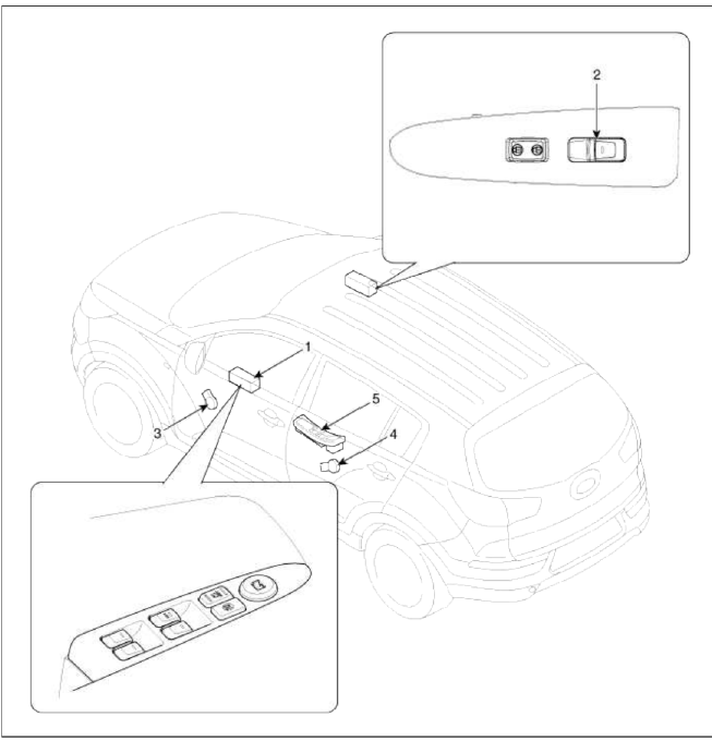
- Driver power window main switch
- Passenger window switch
- Front window motor
- Rear window motor
- Rear window switch
Description and Operation
Operation
Function Of Safety Power Window
When all door (Front, Rear) power window auto-up switch is operated, safety function is activated.
1. Safety function condition.
When detect the force of 100N during the window using, window is reversed.
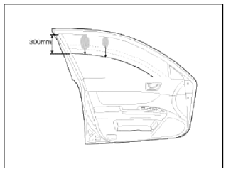
2. Length of window reversing (except holding the auto-up switch).
- When detect the jamming during the 4mm ~ 250mm from top of the door.
→ Window is reversed until 300mm from top of the door.
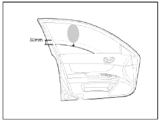
- When detect the jamming over the 250mm from top of the door.
→ Window is reversed until 50mm from jamming position.
→ Window is reversed 50mm or bottom position in case of 50mm reversing distance.
- When detect the jamming over 300mm from top of the door.
→ Window stops at reverse point.
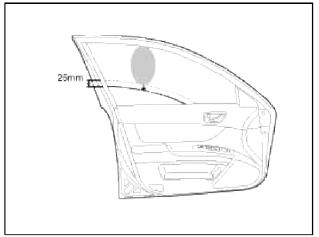
3. Length of window reversing (holding the auto-up switch)
- When detect the jamming during holding the auto-up switch.
→ Window is reversed until 25mm from jamming position.
- Auto-up function is not available during the 5 seconds from above condition.
→ When holding the auto-up switch, window is operated as a manual-up function. (Safety function is not activated.)
- When detect the jamming during holding the auto-up switch again.
→ Window is reversed until 25mm from jamming position.
- When holding the auto-up switch after 5 seconds from above condition.
→ Window is reverse until 25mm from jamming position.
4. Safety function is not available area
Safety function is not available during the 4mm from top of the door.
Initializing Method Of The Safety Power Window
1. Position counter and position initialization
- Position counter
Window position counting is implemented by use of one Hall Effect sensor (HEF) connected to timer capture unit of the Controller with a resolution of 180º electrical.Even the battery was separated from the car, it must keep the window position information.
- Position initialization For position initialization, position counter detect the upper mechanical stop and lower mechanical Position.
Motor control unit (MCU) allow only Manual mode activity (without ASD Anti-Squeeze Detection algorithm) feature) before to be initialized.
Initialization means the condition to move the window system with full anti-pinch function and related functions by detecting the window travel distance (Upper/Lower mechanical limits).
Conditions for initialization are
- de-initialized position counter
- Power window switch Up activated
- block condition detected (no motor movement of more than 1 count during 1sec/ SW dependent)
Switch action with De-initialized condition:
- Up direction: Manual & Auto P/WDW sw input → manual mode;
- Down direction: Manual P/WDW sw input → manual mode, + Auto s/w input → auto mode
- Re-initialization
During re-initialization, position counter is set to "zero" at upper block position to compensate counting errors by software, mechanical tolerances or physics. Conditions for re-initialization are
- initialized position counter.
- window at upper block position (capture range EEPROM programmable)
- block condition detected (no motor movement of more than 1 count during 1sec/ SW dependent)
- De-initialization
The system initialization/calibration will be lost in the following cases:
- After parameter modification via diagnostic
- Wrong EEPROM checksum at ECU wake-up or power-on
- Movement outside predefined window stroke (above learned top position, below predefined bottom position)
- De-initialization after a defined number (EEPROM) of reversals without re-initialization in the upper seal (activation /de-activation controlled by EEPROM value). A window down movement or switching off the window lifter permission resets the reversal counter value (activation by EEPROM bit).
- De-initialization after a defined number of movements (EEPROM) without re-initialization in the upper seal (activation /de-activation controlled by EEPROM value)
- Special de-initialization procedure: The special window lifter de-initialization procedure works as follows:
- System is initialized
- Move window below soft-stop position (position EEPROM adjustable)
- Press MANU-down switch and keep it pressed
- Apply permission signal (serial-link = PIN 6) ON → OFF → ON within 2 seconds (time EEPROM adjustable)
- Soft stop function
In order to reduce noise and mechanical stress, the window movement is stopped under control of the ECU before the bottom position is reached.The clearance is 0 / +10 mm (at 11.5 V to 14.5 V).
To activate the soft bottom stop function, the top reference position and bottom reference position have to be initialized. Therefore, the window is lifted into the top position until the block condition is detected. This position is taken as top reference position.
Afterwards, the window is moved to the bottom position until the block condition is detected (mechanical stop). This position is taken as bottom reference position.
The bottom reference position is re-initialized:
- When window is operated down stalling from soft stop position
- Every "9" stops at soft stop position.
- Thermal protection
Thermal protection by software module is implemented to prevent from destruction of motor during overload condition. Motor temperature is estimated by integrating squared motor current as an estimate for heating power integral. When estimated motor temperature exceeds EEPROM programmable upper limit, motor is deactivated for fixed delay tune (default value = 30 sec.) Thermal shutdown during a window operation will not interrupt the operation due to safety reasons. - Operation tune limiter Maximal operation time of power window motor is limited to 15 sec (EEPROM programmable).
- Continuous reverse
Current Number of Continuous reverse of window is 5. With the below condition, this counter Will be initialized.
- IG OFF
- DOWN signal ON
- WINDOW CLOSE
READ NEXT:
 Power Window Motor | Power Window Switch
Repair procedures
Inspection
Front Power Window Motor
1. Remove (-) negative battery terminal.
2. Remove the front door trim.
(Refer to the BD group - "Front door")
3. Disconnect
SEE MORE:
Auto control
The rain sensor (A) located on the upper
end of the windshield glass senses the
amount of rainfall and controls the wiping
cycle for the proper interval. The
more it rains, the faster the wiper operates.
When the rain stops, the wiper
stops.
To vary the speed setting, turn the
speed
Operating HomeLink
Operating HomeLink
1) Operating HomeLink
Press and release the desired programmed
HomeLink button (1, 2 or 3).
NOTICE
The HomeLink indicator (7) should light
green, solid or flashing, and your programmed
device should operate.
If your device does not operate, the
HomeLink prog
Content
- Home
- Kia Sportage - Fifth generation (NQ5) - (2022-2026) - Owner's Manual
- Kia Sportage - Second generation (JEKM) (2005-2015) - Body Workshop Manual
- Kia Sportage Third generation (SL) - (2011-2016) - Service and Repair Manual
- Sitemap
- Top articles
