Kia Sportage: Components and Components Location | Front Strut Assembly
Components Location
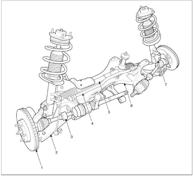
- Front axle
- Front lower arm
- Drive shaft
- Stabilizer bar
- Steering gearbox
- Sub frame
- Front strut assembly
Front Strut Assembly
Components and Components Location
Components
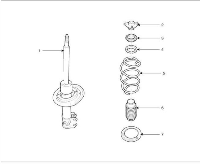
- Strut assembly
- Insulator
- Bearing
- Spring upper pad
- Spring
- Dust cover
- Spring lower pad
Repair procedures
Replacement
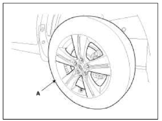
1. Remove the front wheel & tire.
Tightening torque: 88.3 ~ 107.9N.m (9.0 ~ 11.0kgf.m, 65.1 ~ 79.6lb-ft)
CAUTION
Be careful not to damage to the hub bolts when removing the front wheel & tire (A).
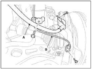
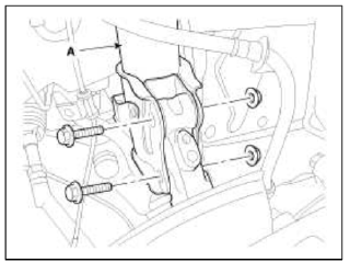
2. Remove the brake hose (A) & wheel speed sensor bracket (B) from the front stint assembly by loosening mounting bolts.
3. Disconnect the stabilizer link (B) from the front stint assembly (A) after loosening the nut.
Tightening torque: 98.1 ~ 117.7N.m (10.0 ~ 12.0kgf.m, 72.3 ~ 86.8lb-ft)
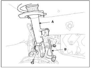
4. Disconnect the front strut assembly (A) with the knuckle by loosening the bolt & nut.
Tightening torque: 137.3 ~ 156.9N.m (14.0 ~ 16.0kgf.m, 101.3 ~ 115.7lb-ft)
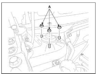
5. Remove the front strut assembly and then loosen the stint mounting nuts (A).
Tightening torque: 44.1 ~ 58.8N.m (4.5 ~ 6.0kgf.m, 32.5 ~ 43.4lb-ft)
6. Installation is the reverse of removal.
Disassembly
1. Using the special tool (09546-26000), compress the coil spring (A).
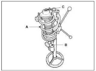
2. Remove the self-locking nut (C) from the strut assembly (B).
3. Remove the insulator, spring seat, coil spring and dust cover from the strut assembly.
4. Reassembly is the reverse of the disassembly
Inspection
1. Check the shut bearing for wear and damage.
2. Check the spring upper and lower seat for damage and deterioration.
3. Compress and extend the piston rod (A) and check that there is no abnormal resistance or unusual sound during operation.
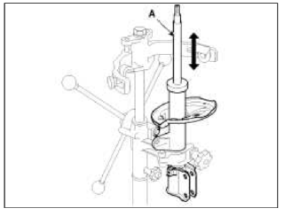
Disposal
1. Fully extend the piston rod.
2. Drill a hole on the A section to remove gas from the cylinder.
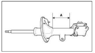
CAUTION
The gas corning out is harmless, but be careful of drips that may fly when drilling.
Be sure to wear safety goggles or eye protection when performing this task.
READ NEXT:
 Front Lower Arm | Front Stabilizer Bar
Repair procedures
Replacement
1. Remove the front wheel & tire.
Tightening torque: 88.3 ~ 07.9N.m (9.0 ~ 11.0kgf.m, 65.1 ~ 79.6lb-ft)
CAUTION
Be careful not to damage to the hub bolts
SEE MORE:
Valve Body
Description and Operation
Description
The valve body is essential to automatic transaxle control and consists of
various valves used to control the oil feed
from the oil pump. Specifically, these valves consist of pressure regulator
valves, oil redirection valves, shift valves,
and man
Front Seat
Components and Components
Location
Components
Headrest
Headrest guide
Front seat back cover
Front seat back heater
Front seat back pad
Front seat back power lumbar
Front seat back duct
Front seat back frame
Front seat back cover
Front seat map pocket
Front inside co
Content
- Home
- Kia Sportage - Fifth generation (NQ5) - (2022-2026) - Owner's Manual
- Kia Sportage - Second generation (JEKM) (2005-2015) - Body Workshop Manual
- Kia Sportage Third generation (SL) - (2011-2016) - Service and Repair Manual
- Sitemap
- Top articles
