Kia Sportage: SRS Control Module (SRSCM)
Description and Operation
Description
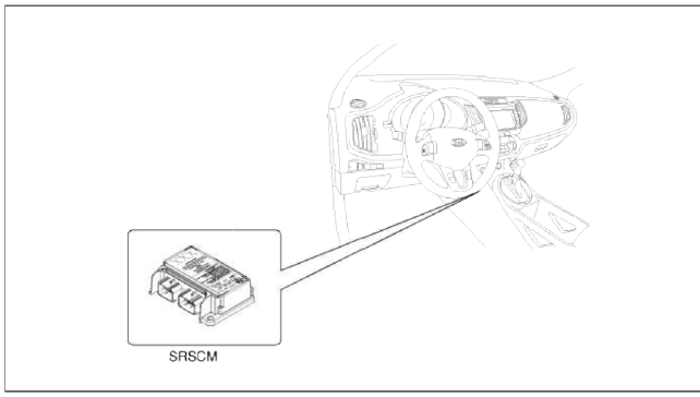
The primary purpose of the SRSCM (Supplemental Restraints System Control Module) is to discriminate between an event that warrants restraint system deployment and an event that does not. The SRSCM must decide whether to deploy the restraint system or not. After determining that pretensioners and/or airbag deployment is required, the SRSCM must supply sufficient power to the pretensioners and airbag igniters to initiate deployment.
The SRSCM determines that an impact may require deployment of the pretensioners and airbags from data obtained from impact sensors and other components in conjunction with a sating function.
The SRSCM will not be ready to detect a crash or to activate the restraint system devices until the signals in the SRSCM circuitry stabilize.
It is possible that the SRSCM could activate the safety restraint devices in approximately 2 seconds but is guaranteed to fully function after prove-out is completed.
The SRSCM must perform a diagnostic routine and light a system readiness indicator at key-on. The system must perform a continuous diagnostic routine and provide fault annunciation through a warning lamp indicator in the event of fault detection. A serial diagnostic communication interface will be used to facilitate servicing of the restraint control system.
Components and Components Location
Components
Repair procedures
Removal
1. Remove the ignition key from the vehicle.
2. Disconnect the battery negative cable and wait for at least thee minutes before beginning work.
3. Disconnect the DAB, PAB, SAB, CAB and BPT connectors.
4. Remove the floor console upper cover. (Refer to the Body group - console)
5. Remove the shift lever assembly. (Refer to the transaxle system group - shift lever)
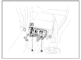
6. Pull the lock (1) forward and then pull the lever (3) after pressing the lever lock (2).
Disconnect the airbag system control module connector. (A and B)
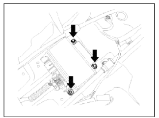
7. Remove the SRSCM mounting nuts (3EA) from the SRSCM, then remove the SRSCM.
CAUTION
You must remove or install SRSCM at the ignition switch OFF because SRSCM has overturn sensing function. SAB, CAB, BPT may be deployed if you shake SRSCM at the direction of up and down or right and left at the ignition switch ON.
Installation
1. Remove the ignition key from the vehicle.
2. Disconnect the battery negative cable and wait for at least thee minutes before beginning work.
3. Install the SRSCM with the SRSCM mounting nuts.
Tightening torque: 6.8 ~ 9.2 N.m (0.7 ~ 0.9 kgf.m, 5.0 ~ 6.8 lb-ft)
NOTE
Use new mounting bolts when replacing the SRSCM after a collision.
4. Connect the SRSCM harness connector.
5. Install the shift lever assembly. (Refer to the transaxle system group - shift lever)
6. Install the floor console upper cover. (Refer to the Body group - console)
7. Connect the DAB, PAB, SAB, CAB and BPT connectors.
8. Reconnect the battery negative cable.
9. After installing the SRSCM, confirm proper system operation:
- Turn the ignition switch ON: the SRS indicator light should be turned on for about six seconds and then go off.
CAUTION
SRSCM can sense a vehicle rollover. SAB, CAB, BPT can deploy if mechanic moves the SRSCM on vehicle during IGN ON state. For this reason, be sure to dun the IGN OFF and then remove the SRSCM from vehicle.
Variant coding
After replacing the SRSCM with a new one, the "Variant Coding" procedure must be preformed.
NOTE
1. On SRSCM valiant coding mode, the airbag warning lamp is periodically blinking (ON: 0.5sec., OFF: 0.5sec.) until the coding is normally completed.
2. If the valiant coding is failed. DTC Ð’1762 (ACU Coding Error) will be displayed and the warning lamp will be turned on.
In this case, perform the variant coding procedure again after continuing the cause in "DTC Fault State Information".
Variant Coding can be perforated up to 255 times, but if the number of coding work exceeds 255 times, DTC Ð’1683 (Exceed Maximum coding Number) will be displayed and SRSCM must be replaced.
3. If the battery voltage is low (less than 9 V), DTC Ð’1102 will be displayed. In this case, charge the battery before anything else, and then perform the valiant coding procedure.
DTC Ð’1762 (ACU Coding Error) and Ð’1102 (Battery Voltage Low) may be displayed simultaneously.
Valiant coding Procedure
â– On-Line type on GDS
1. Ignition "OFF", connect GDS.
2. Ignition "ON" & Engine "OFF" select vehicle name and airbag system.
3. Select Valiant coding mode.
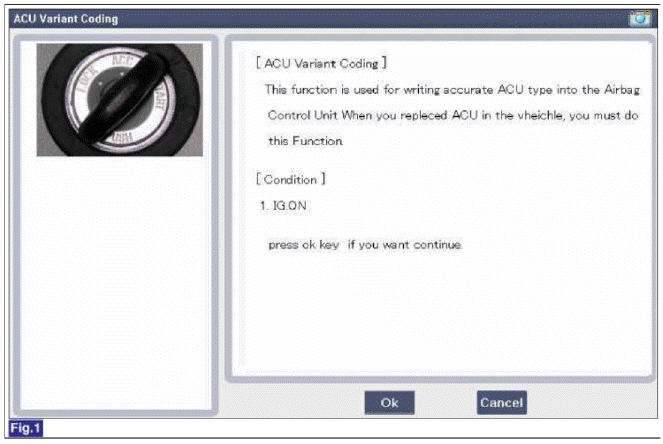
4. Follow steps on the screen as below.
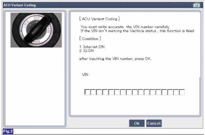
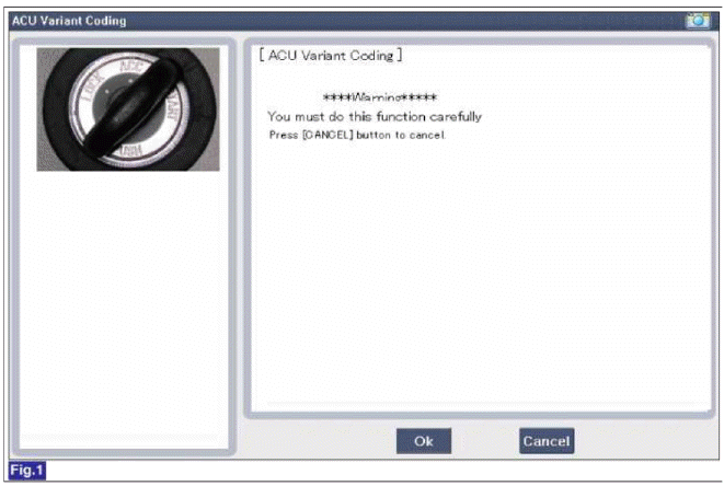
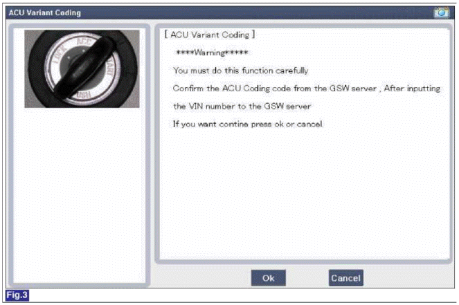
- Initial ACU Valiant Coding screen
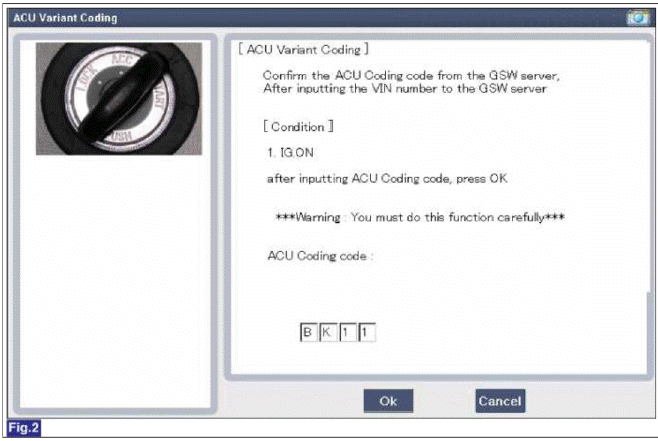
- VIN Code entering screen
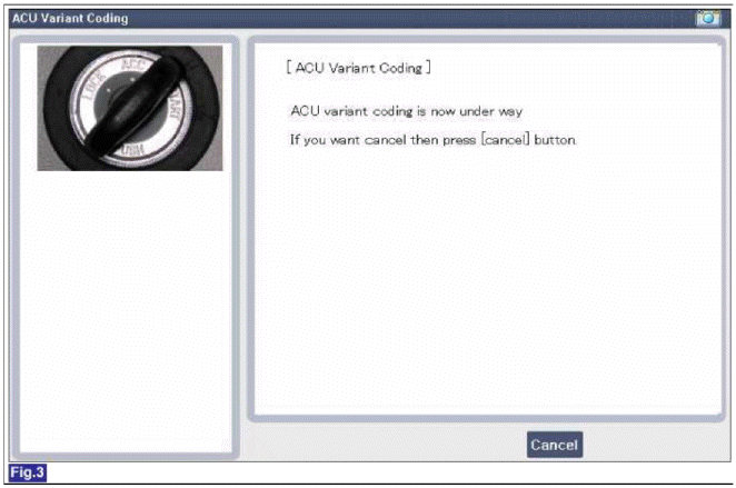
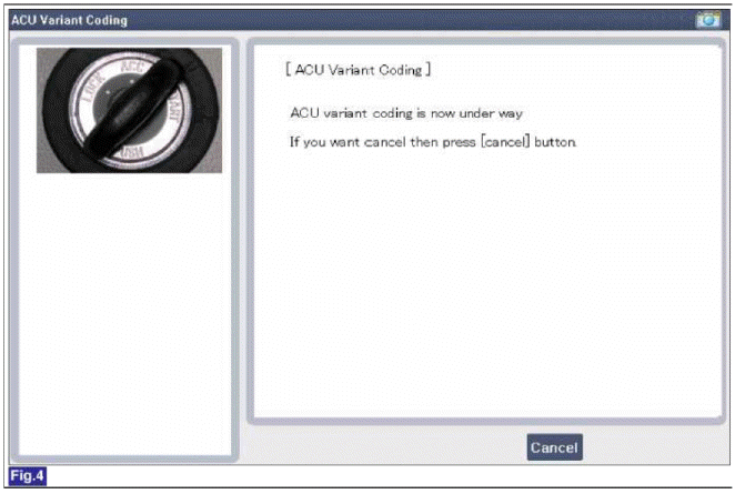
- Variant coding's proceeding screen-1
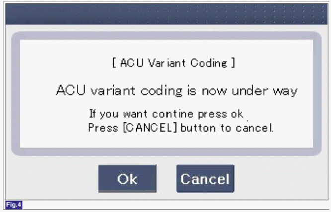
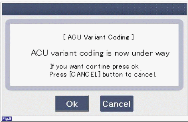
- Variant coding's proceeding screen-2
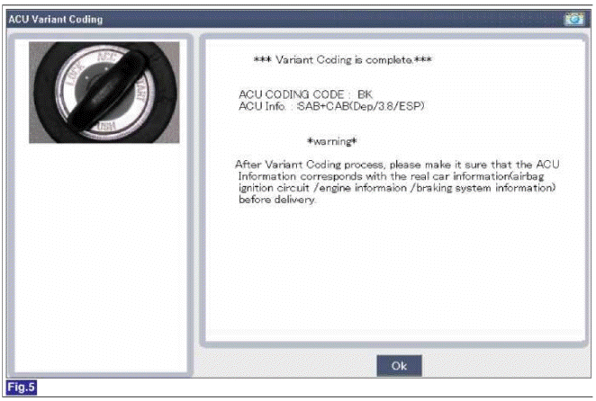
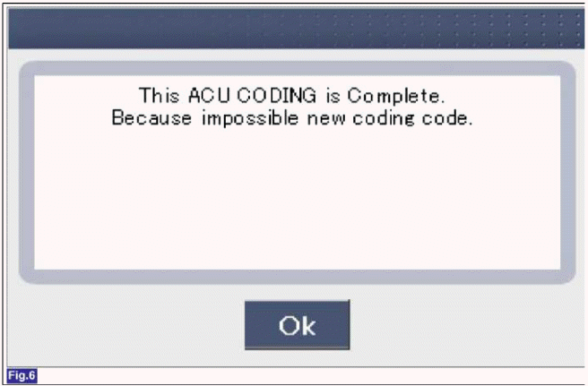
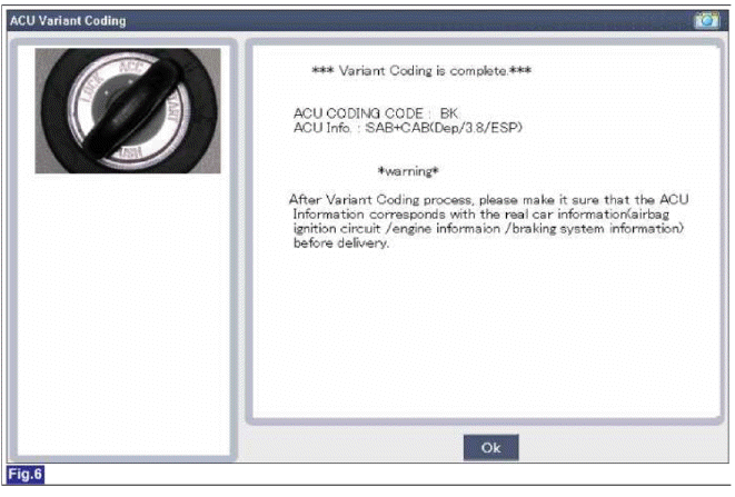
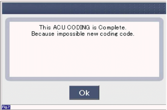
- Variant coding is completed
NOTE
- This screen is opened when yon try the variant coding again on the SRSCM which has bee performed variant coding.
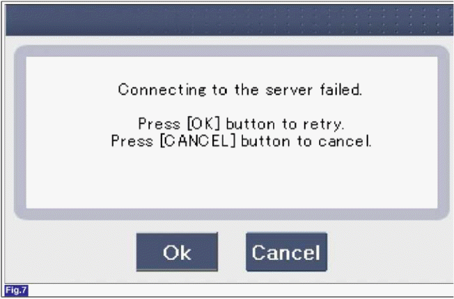
- Screen of communication failure.
â– Off-line type on GDS (This can be used when not connecting to internet)
- Initial ACU Variant Coding screen
- ACU Coding Code entering screen
- Screen of rechecking ACU Coding code's entering
- Variant coding's proceeding screen-1
- Variant coding's proceeding screen-2
- Variant coding is completed
NOTE
- This screen is opened when yon try the variant coding again on the SRSCM which has bee performed variant coding.
READ NEXT:
 Front Impact Sensor (FIS)
Description and Operation
Description
The front impact sensor (FIS) is installed in the Front End Module (FEM).
They are remote sensors that detect
acceleration due to a collision at its mo
Side Impact Sensor (SIS)
Description and Operation
Description
Side Impact Sensor (SIS) system consists of two P-SIS which are installed at
each center of the front door module
(LH and RH) and two SIS which are ins
Seat Belt Buckle Switch (BS) | Passive Occupant Detection System (PODS)
Description and Operation
Description
The SRSCM shall monitor the status of the driver and front passenger seat belt buckle. The SRSCM provides one pin each for the driver and front passenger
SEE MORE:
Components and Components Location | Repair procedures
Components (1)
Brake booster
Master cylinder assembly
O-ring
Components (2)
[2.0T - GDI ENGINE ONLY]
Vacuum pump
Bracket
Repair procedures
Brake Booster Operating Test
For simple checking of the brake booster operation, carry out the foll
Components and ComponentsLocation | Repair procedures
Components
Front driveshaft (LH)
Inner shaft
Front driveshaft (RH)
[LH]
Split pin
Castle nut
Washer
BJ assembly
Clip A
Ð’J boot band
Ð’J boot
Dynamic damper band
Dynamic damper
Shaft
VTJ boot band
Content
- Home
- Kia Sportage - Fifth generation (NQ5) - (2022-2026) - Owner's Manual
- Kia Sportage - Second generation (JEKM) (2005-2015) - Body Workshop Manual
- Kia Sportage Third generation (SL) - (2011-2016) - Service and Repair Manual
- Sitemap
- Top articles
