Kia Sportage: Description and Operation | Catalytic Converter | CVVT (Continuously Variable Valve Timing) System
Description
Exhaust emissions (CO, HC, NOx) are controlled by a combination of engine modifications and the addition of special control components.
Modifications to the combustion chamber, intake manifold, camshaft and ignition system form the basic control system.
These items have been integrated into a highly effective system which controls exhaust emissions while maintaining good drivability and fuel economy.
Air/Fuel Mixture Control System [Multiport Fuel Injection (MFI) System]
The MFI system uses signals from the heated oxygen sensor to activate and control the injector installed in the manifold for each cylinder, thus precisely regulating the air/fuel mixture ratio and reducing emissions.
This in turn allows the engine to produce exhaust gas of the proper composition to permit the use of a three way catalyst. The three way catalyst is designed to convert the three pollutants [hydrocarbons (HC), carbon monoxide (CO), and oxides of nitrogen (NOx) ] into harmless substances. There are two operating modes in the MFI system.
1. Open Loop аіr/fuel ratio is controlled by information pre-programmed into the ECM.
2. Closed Loop air/fuel ratio is constantly adjusted by the ECM based on information supplied by the oxygen sensor.
Catalytic Converter
Description and Operation
Description
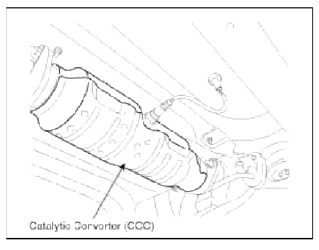
The catalytic converter of the gasoline engine is a three way catalyst. It oxidizes carbon monoxide and hydrocarbons (HC), and separates oxygen from the oxides of nitrogen (NOx).
There are two types of three-way catalyst; Palette type and Monolith type.
CVVT (Continuously Variable Valve Timing) System
Description and Operation
Description
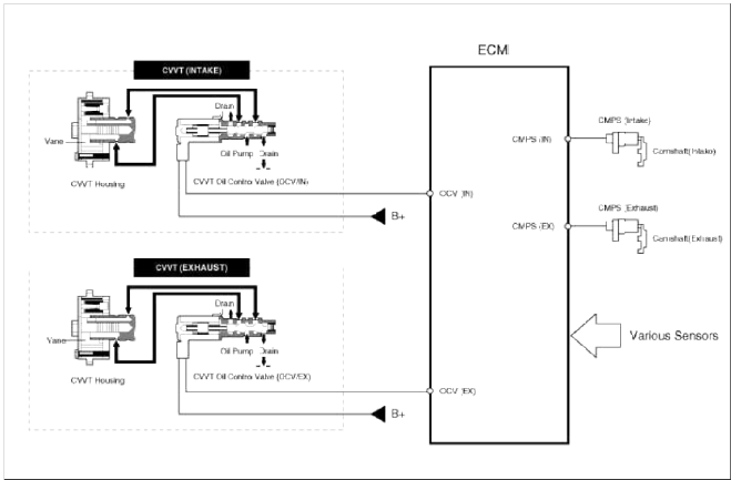
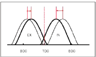
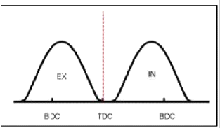
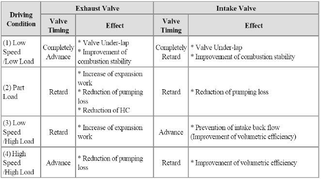
Continuous Variable Valve Timing (CWT) system advances or retards the valve timing of the intake and exhaust valve in accordance with the ECM control signal which is calculated by the engine speed and load.
By controlling CWT, the valve over-lap or under-lap occurs, which makes better fuel economy and reduces exhaust gases (NOx, HC) and improves engine performance through reduction of pumping loss, internal EGR effect, improvement of combustion stability, improvement of volumetric efficiency, and increase of expansion work.
This system consist of
- the CVVT Oil Control Valve (OCV) which supplies the engine oil to the cam phaser or runs out the engine oil from the cam phaser in accordance with the ECM PWM (Pulse With Modulation) control signal.
- and the Cam Phaser winch varies the cam phase by using the hydraulic force of the engine oil.
The engine oil getting out of the CVVT oil control valve varies the cam phase in the direction (Intake Advance/Exhaust Retard) or opposite direction (Intake Retard/Exhaust Advance) of the engine rotation by rotating the rotor connected with the camshaft inside the cam phaser.
Operation Principle
The CVVT has the mechanism rotating the rotor vane with hydraulic force generated by the engine oil supplied to the advance or retard chamber in accordance with the CVVT oil control valve control.
![[CVVT System Mode]](images/books/1921/16/index%20156.png)
[CVVT System Mode]
- Low Speed / Low Load

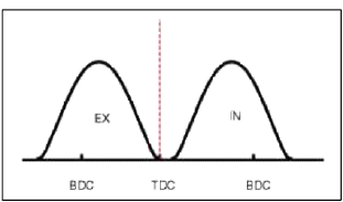
- Part Load
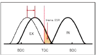
- Low Speed / High Load
- High Speed / High Load
READ NEXT:
SEE MORE:
 Auto defogging system
Auto defogging helps reduce the possibility
of fogging up the inside of the
windshield by automatically sensing the
moisture on inside the windshield.
The auto
defogging system operates
when the heater or air conditioning
is on.
When the Auto Defogging System operates,
the indicator
 Components and Components Location | Removal - Repair procedures
Components
Intake camshaft
Exhaust camshaft
Intake CVVT assembly
Exhaust CVVT assembly
Timing chain
Timing chain guide
Timing chain tensioner arm
Timing chain tensioner
Timing chain oil jet
Balance shaft chain
Balance shaft chain tensi
Content
- Home
- Kia Sportage - Fifth generation (NQ5) - (2022-2026) - Owner's Manual
- Kia Sportage - Second generation (JEKM) (2005-2015) - Body Workshop Manual
- Kia Sportage Third generation (SL) - (2011-2016) - Service and Repair Manual
- Sitemap
- Top articles