Kia Sportage: Fuel Pump
Repair procedures
Inspection
[Fuel pump]
1. Turn the ignition switch OFF, and then remove battery (-) cable.
2. Remove the fuel pump assembly.
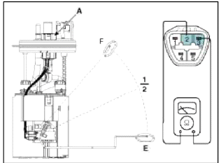
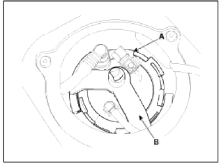
3. Check motor operation by fuel pump connector (A) connecting power (No.4) and ground (No.5).

- -
- Fuel sender signal
- Fuel sender ground
- Fuel pump motor (+)
- Fuel pump motor ground
[Fuel sender]
1. Trim the ignition switch OFF, and then remove battery (-) cable.
2. Remove the fuel pump assembly.
3. Using an ohmmeter, measure the resistance between terminals 2 and 3 of sender connector (A) at each float level.
- -
- Fuel sender signal
- Fuel sender ground
- Fuel pump motor (+)
- Fuel pump motor ground
4. Also check that the resistance changes smoothly when the float is moved from "E" to "F".
Removal
1. Release the residual pressure in fuel line (Refer to "Release Residual Pressure in Fuel Line" in this group).
2. Remove the rear seat (Refer to "Seat" in BD group).
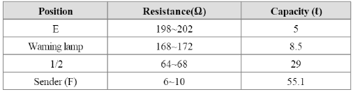
3. Remove the fuel pump service cover (A).
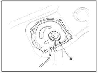
4. Disconnect the fuel pump connector (A) and the fuel tank pressure sensor connector (B).
5. Disconnect the fuel feed tube quick connector (C) and the vapor tube quick-connector (D).
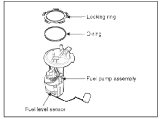
6. Remove locking ring (A) by using the special service tool (B) [No.:09310-2S200].
Fuel pump locking ring loosening torque: Min. 68.65 M.m (Min. 7 kgf.m. Min. 50.6 lb-ft)
7. Remove the fuel pump from the fuel tank.
Installation
1. Installation is reverse of removal.
CAUTION
Be careful of fuel pump direction when installing (Refer to the groove in the fuel tank).
READ NEXT:
 Filler-Neck Assembly | Accelerator Pedal | Delivery Pipe
Repair procedures
Removal
1. Remove the rear-LH wheel, tire, and the inner wheel house.
2. Disconnect the fuel filler hose (A) and the ventilation hose (B).
3. Open the fuel filler door and unfa
SEE MORE:
Side Body | Interior
Body Repair
Side Body A
* These dimensions indicated in this figure are actual-measurement dimensions.
Side Body Ð’
* These dimensions indicated in this figure are actual-measurement dimensions.
Interior
Body Repair
Interior A
* These dimensions indic
Components and Components Location | Steering Column and Shaft
Components
Steering wheel
Steering column
ECU
Motor
Steering gear box
MDPS Circuit Diagram
Harness Connector
Battery
Battery -
Battery +
Vehicle
IGN
-
-
Content
- Home
- Kia Sportage - Fifth generation (NQ5) - (2022-2026) - Owner's Manual
- Kia Sportage - Second generation (JEKM) (2005-2015) - Body Workshop Manual
- Kia Sportage Third generation (SL) - (2011-2016) - Service and Repair Manual
- Sitemap
- Top articles
