Kia Sportage: Filler-Neck Assembly | Accelerator Pedal | Delivery Pipe
Repair procedures
Removal
1. Remove the rear-LH wheel, tire, and the inner wheel house.
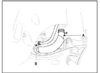
2. Disconnect the fuel filler hose (A) and the ventilation hose (B).
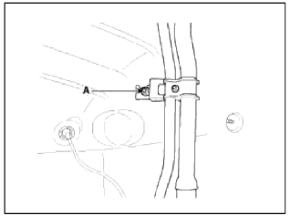
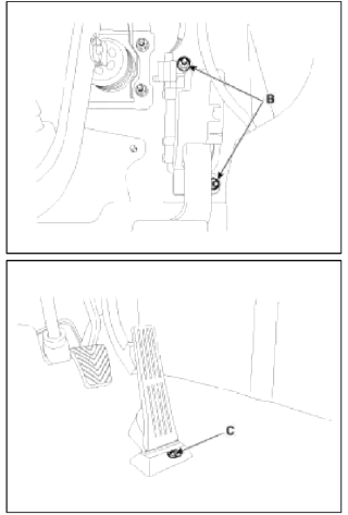
3. Open the fuel filler door and unfasten the filler-neck assembly mounting screw (A).
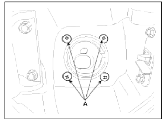
4. Remove the filler-neck assembly from the vehicle after removing the bracket mounting nut (A).
Installation
1. Installation is reverse of removal.
Filler-neck assembly bracket installation nut: 3.9 ~ 5.9 N.m (0.4 ~ 0.6 kgf.m 2.9 ~ 4.3 lb-ft)
Accelerator Pedal
Repair procedures
Removal
1. Turn the ignition switch OFF and disconnect the negative (-) battery cable.
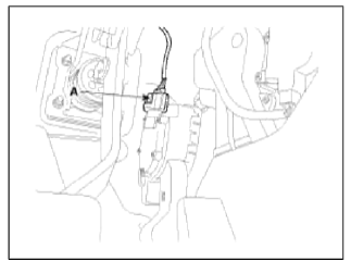
2. Disconnect the accelerator position sensor connector (A).
3. Remove the installation nuts (B), the bolt (C) and then remove the accelerator pedal module.
Installation
1. Installation is reverse of removal.
Accelerator pedal module installation nut: 16.7 ~ 25.5 N.m (1.7 ~ 2.6 kgf.m, 12.3 ~ 18.8 lb-ft)
Accelerator pedal module installation bolt: 7.8 ~ 11.8 N.m (0.8 ~ 1.2 kgf.m, 5.8 ~ 8.7 lb-ft)
Delivery Pipe
Repair procedures
Removal
WARNING
In case of removing the high pressure fuel pump, high pressure fuel pipe, delivery pipe, and injector, there may be injury caused by leakage of the high pressure fuel. So don't do any repair work right after engine stops.
1. Turn the ignition switch OFF and disconnect the battery negative (-) cable.
2. Release the residual pressure in fuel line (Refer to "Release Residual Pressure in Fuel Line" in this group).
CAUTION
When removing the fuel pump relay, a Diagnostic Trouble Code (DTC) may occur. Delete the code with the GDS after completion of "Release Residual Pressure in Fuel Line" work.
3. Remove the intake manifold (Refer to "Intake And Exhaust System" in EM group).
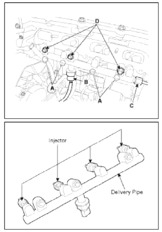
4. Disconnect the injector connectors (A) and the rail pressure sensor connector (B).
5. Remove the high pressure fuel pipe (C).
6. Remove the installation bolt (D), and then remove the delivery pipe and injector assembly from the engine.
Installation
CAUTION
- Install the component with the specified torques.
CAUTION
- Apply engine oil to the injector O-ring.
- Do not use already used injector О-ring again.
CAUTION
- Do not reuse the bolts.
CAUTION
- When insert the injector, be careful not to damage the injector tip.
CAUTION
- Use proper tooling for change of combustion seal. Take proper precautions not to damage surface during assembly or disassembly.
CAUTION
- Avoid dropping the fuel pipe (including injectors) or bumping it into any hard objects since damage to the internal components may occur. If necessary, visually inspect and confirm proper operation with performance tests prior to reuse.
- Before installing the injector into the cylinder head, clean the injector hole and avoid contaminants from entering inside the injector hole. When installing the injector, avoid bumping the injector tip into any of the surrounding components since the tip may become damaged from the impact.
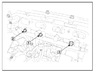
- When fastening the there fuel delivery pipe mounting bolts, fully hand-tighten first, and then tighten in the proper sequence ( (1) → (2) → (3) ) in several cycles up to the specified torque. The delivery pipe should move less than 1/8 inch (аррrох. 3mm). whenever each bolt is tightened.
1. Installation is reverse of removal.
Delivery pipe installation bolt: 18.6 ~ 23.5 N.m (1.9 ~ 2.4 kgf.m, 13.7 ~ 17.4 lb-ft)
High pressure fuel pipe installation nut: 26.5 ~ 32.4 N.m (2.7 ~ 3.3 kgf.m, 19.5 ~ 23.9 lb-ft)
READ NEXT:
 High Pressure Fuel Pump
Repair procedures
Removal
WARNING
In case of removing the high pressure fuel pump, high pressure fuel pipe,
delivery pipe, and injector, there may be
injury caused by leakage of the high pressur
SEE MORE:
General Information
Specifications
Specifications
VFS: Variable Force Solenoid
Sensors
Input Speed Sensor
Type: Hall effect sensor
Specifications
Output Speed Sensor
Type: Hall effect sensor
Specifications
Oil Temperature Sensor
Type: Negative thermal coefficien
Repair procedures | Components and Components Location | Transaxle Control Module (TCM)
Adjustment
TCM Learning
When shift shock is occurred or parts related with the transaxle are replaced. TCM learning should be performed.
In the following case, TCM learning is required.
Transaxle assembly replacement
TCM replacement
TCM upgrading
1. TCM learning conditi
Content
- Home
- Kia Sportage - Fifth generation (NQ5) - (2022-2026) - Owner's Manual
- Kia Sportage - Second generation (JEKM) (2005-2015) - Body Workshop Manual
- Kia Sportage Third generation (SL) - (2011-2016) - Service and Repair Manual
- Sitemap
- Top articles
