Kia Sportage: General Information
Specifications
Specifications

VFS: Variable Force Solenoid
Sensors
Input Speed Sensor
Type: Hall effect sensor
Specifications
Output Speed Sensor
Type: Hall effect sensor
Specifications
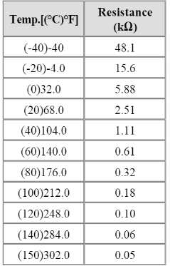
Oil Temperature Sensor
Type: Negative thermal coefficient type
Specifications
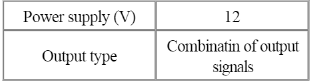
Inhibitor Switch
Type: Combination of output signals from 4 terminals
Specifications
Solenoid Valves
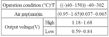
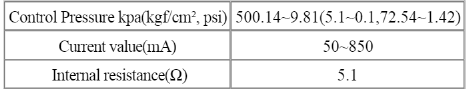
Direct control VFS [26/B, T/CON]
Control type : Normal low type
![Direct control VFS [UD/B, OD/C, 35R/C]](images/books/1921/2/index%206.png)
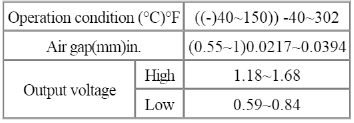
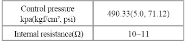
Direct control VFS [UD/B, OD/C, 35R/C]
Control Type: Normal high type
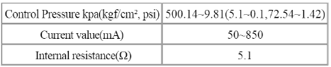
Line Pressure Control VFS
Control type : Normal high type
ON/OFF Solenoid Valve (SS-A, SS-B)
Control type : Normal low type
Solenoid Valve Operation Table
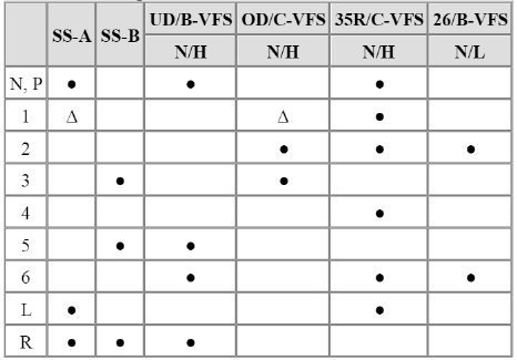
 : Connected status
 : Connected at vehicle speed above 8km/h
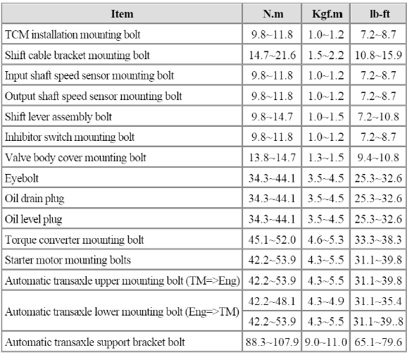
Tightening Torques
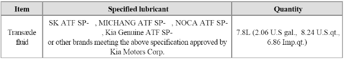
Lubricants
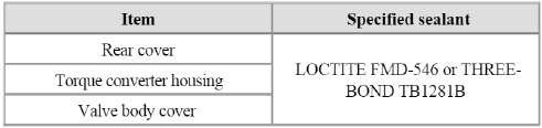
Sealant
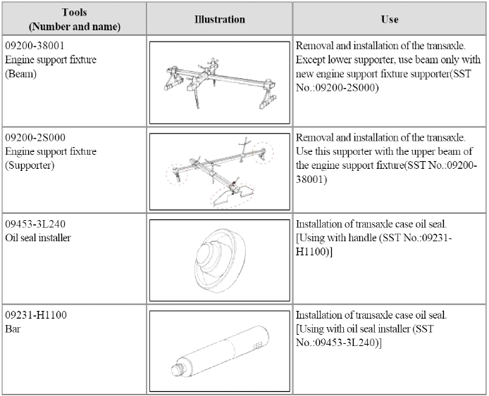
Special Service Tools
Special Service Tools
READ NEXT:
 Components and Components Location
Components Location
Converter housing
Automatic transaxle case
Rear cover
Valve body cover
Manual control lever
Air breather hose
Inhibitor switch
Solenoid valve
connector
SEE MORE:
Valve Body
Description and Operation
Description
The valve body is essential to automatic transaxle control and consists of
various valves used to control the oil feed
from the oil pump. Specifically, these valves consist of pressure regulator
valves, oil redirection valves, shift valves,
and man
Driver Attention Warning settings
Basic function
Driver Attention Warning will help determine
the driver's attention level by analyzing
driving pattern, driving time, etc.
while vehicle is being driven. Driver
Attention Warning will recommend a
break when the driver's attention level
falls below a certain level.
Le
Content
- Home
- Kia Sportage - Fifth generation (NQ5) - (2022-2026) - Owner's Manual
- Kia Sportage - Second generation (JEKM) (2005-2015) - Body Workshop Manual
- Kia Sportage Third generation (SL) - (2011-2016) - Service and Repair Manual
- Sitemap
- Top articles
