Kia Sportage: Components and Components Location
Components Location
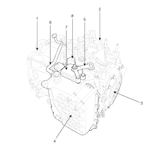
- Converter housing
- Automatic transaxle case
- Rear cover
- Valve body cover
- Manual control lever
- Air breather hose
- Inhibitor switch
- Solenoid valve connector
Repair procedures
Removal
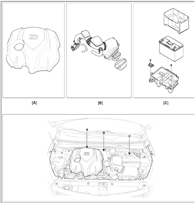
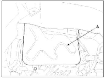
1. Remove the following items;
- Engine cover (A).
- Air cleaner assembly and air duct (B). (Refer to "Intake and Exhaust system" in EM group.)
- Battery and battery tray (C). (Refer to "Charging system" in EE group.)
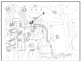
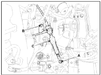
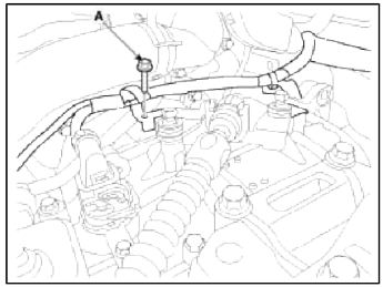
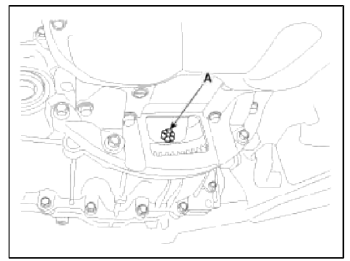
2. Remove the ground line after removing the bolt (A).
3. Disconnect the solenoid valve connector (A) and inhibitor switch connector (B).
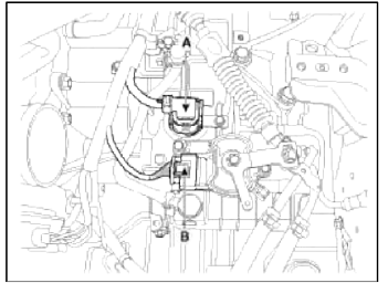
4. Remove the control cable (C) after removing the nut (A) and the bolt (B).
Tightening torque:
(A) 9.8 ~ 14.7 N.m (1.0 ~ 1.5 kgf.m, 7.2 ~ 10.8 lb-ft)
(B) 14.7 ~ 21.6 N.m (1.5 ~ 2.2 kgf.m, 10.9 ~ 15.9 lb-ft)
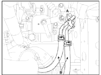
5. Remove the solenoid valve connector and inhibitor switch connector wiring mounting bracket (A).
6. Disconnect the hose (B) after removing the automatic transaxle fluid cooler hose clamp (A).
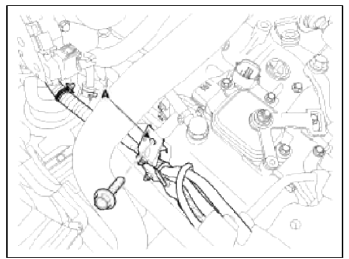
7. Remove the wiring bracket installation bolt (A).
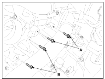
8. Remove the automatic transaxle upper mounting bolt (A-2ea) and the starter motor mounting bolt (B-2ea).
Tightening torque: (A), (B): 42.2 ~ 54.0 N.m (4.3 ~5.5 kgf.m, 31.1 ~ 39.8 lb-ft)
9. Remove the cowl top cover.
(Refer to "Interior (cowl top cover)" in BD group.)
10. Remove the wiper motor.
(Refer to "Windshield Wiper motor" in BE group.)
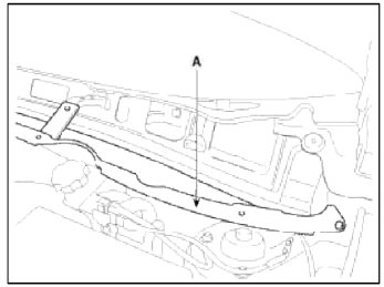
11. Remove the cowl complete assembly panel (A).
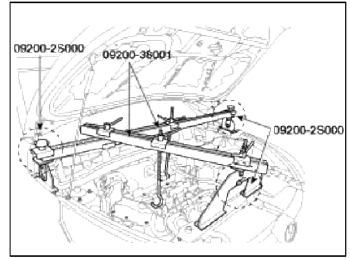
12. Using the engine support fixture (Support SST No.: 09200-2S000, Beam SST No.: 09200-38001), hold the engine and transaxle assembly safely.
13. Remove the automatic transaxle mounting support bracket bolt (A).
Tightening torque: 88.3 ~ 107.9 N.m (9.0 ~ 11.0 kgf.m, 65.1 ~ 79.8 lb-ft)
14. Lift the vehicle with a jack.
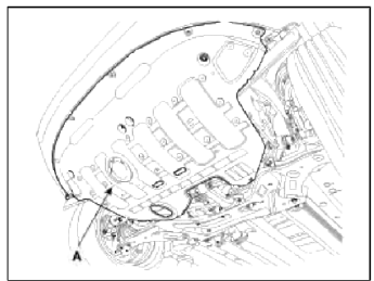
15. Remove the wider cover (A).
Tightening torque: 19.6 ~ 24.5 N.m (2.0 ~ 2.5 kgf.m, 14.5 ~ 18.1 lb-ft)
16. Remove the drive shaft assembly.
(Refer to "Drive shaft assembly" in DS group.)
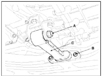
17. Remove the roll rod bracket (C) after removing bolt (A, B).
Tightening torque:
(A) 107.9 ~ 127.5 N.m (11.0 ~ 13.0 kgf.m, 79.6 ~ 94.1 lb-ft)
(B) 49.0 ~ 63.7 N.m (5.0 ~ 6.5 kgf.m, 36.2 ~ 47.0 lb-ft)
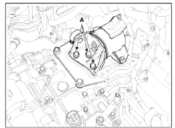
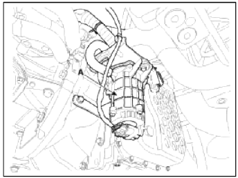
18. Remove the vacuum pump (A).
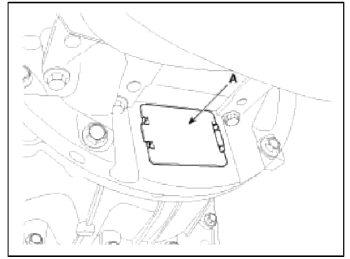
19. Remove the dust cover (A).
20. Remove the torque converter mounting bolt (A-6ea) with rotating the crankshaft.
Tightening torque: 45.1 ~ 52.0 N.m (4.6 ~ 5.3 kgf.m, 33.3 ~ 38.3 lb-ft)
21. Remove the side cover (A).
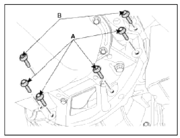
22. Remove the automatic transaxle with a jack after removing the mounting bolt (A-4ea, B-2ea)
Tightening torque:
(A) 42.2 ~ 48.1 N.m (4.3 ~ 4.9 kgf.m, 31.1 ~ 35.4 lb-ft)
(B) 42.2 ~ 54.0 N.m (4.3 ~5.5 kgf.m, 31.1 ~ 39.8 lb-ft)
Installation
1. Installation is the reverse of removal
CAUTION
If the oil seal on the transaxle case side is damaged and fluid is leaking, replace the oil seal with a new unit. When installing the new oil seal, use the specialized tool (oil seal installer, 09453-3L240).
NOTE
After replacement or reinstallation procedure of the automatic transaxle assembly, must perform procedures below.
- Power steering fluid replacement and air bleeding. (Refer to "General information" in ST group)
- Adding automatic transaxle fluid. (Refer to "Hydraulic system (Fluid)" in this group)
- After servicing the automatic transaxle or TCM, clear' the diagnostic
trouble codes (DTC) using the GDS tool.
Diagnostic trouble codes (DTC) cannot be cleared by disconnecting the battery.
- When replacing the automatic transaxle and TCM, reset the diagnostic trouble code by using GDS.
- When deleting diagnostic trouble code, use the GDS as possible.
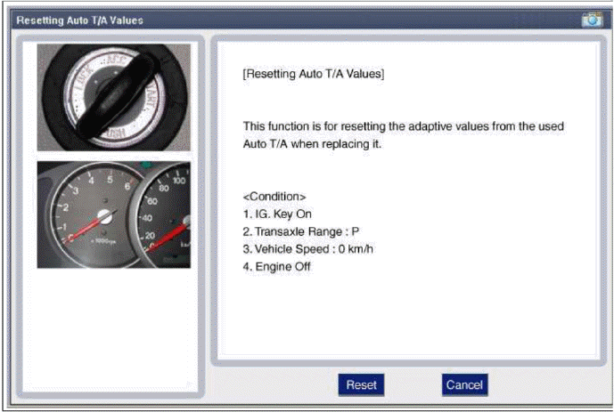
- When replacing the automatic transaxle, reset the automatic transaxle's values by using the GDS.
- Perform TCM learning after replacing the transaxle to prevent slow transaxle response, jerky acceleration and jerky startup. (Refer to "Automatic transaxle control system (Repair procedures)" in this group).
NOTE
- When replacing the automatic transaxle, reset the automatic transaxle's values by using the GDS.[Condition]
- IG Key On
- Transaxle Range: P
- Vehicle Speed: 0 km/h
- Engine Off
READ NEXT:
 Description and Operation, Components and Components Location | Oil Pump | Fluid
Description and Operation
Description
The hydraulic system consists of oil, an oil filter, an oil pump, and a valve body (valves and solenoid valves). The oil pump is powered by the engine. A
SEE MORE:
Navigation-based Smart Cruise Control operation
Operating conditions
Navigation-based Smart Cruise Control
is ready to operate if all of the following
conditions are satisfied:
Smart Cruise Control is operating
Driving on main roads of highways (or
motorways)
WARNING
Navigation-based Smart Cruise Control
(NSCC) is a supplemental s
Navigation-based Smart Cruise Control limitations
Navigation-based Smart Cruise Control
may not operate normally under the following
circumstances:
The navigation is not working properly
Map information is not transmitted
due to infotainment system's abnormal
operation
Speed limit and road information in
the navigation is not up
Content
- Home
- Kia Sportage - Fifth generation (NQ5) - (2022-2026) - Owner's Manual
- Kia Sportage - Second generation (JEKM) (2005-2015) - Body Workshop Manual
- Kia Sportage Third generation (SL) - (2011-2016) - Service and Repair Manual
- Sitemap
- Top articles
