Kia Sportage: Heater & A/C Control Unit (Manual, Full Automatic)
Components and Components Location
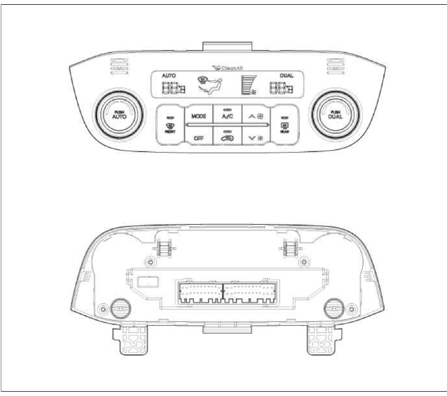
Components
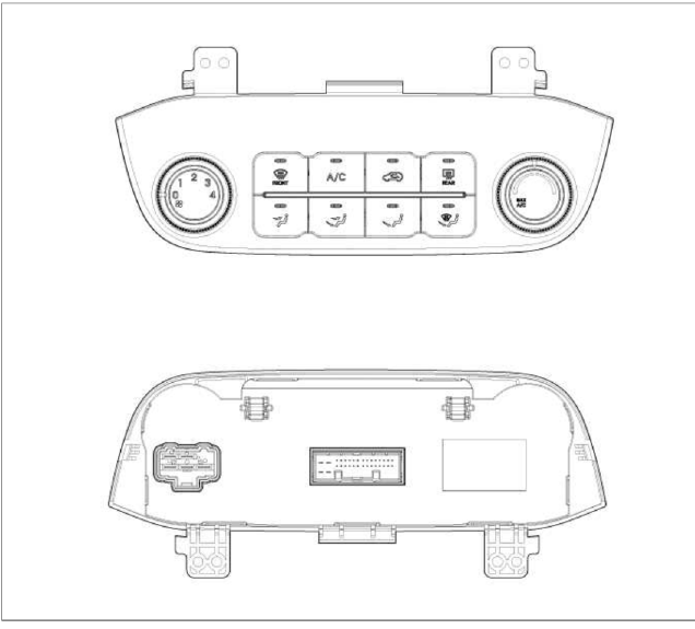
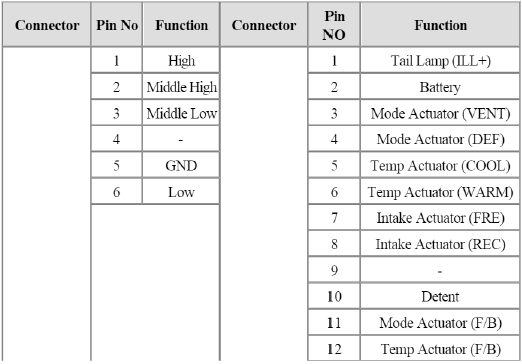
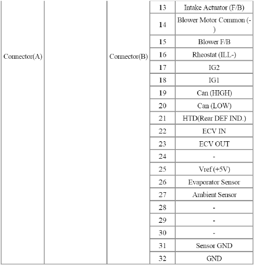
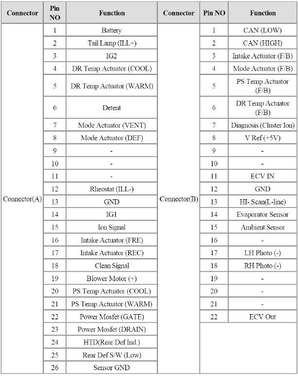
Connector Pin Function
Repair procedures
Replacement
1. Disconnect the negative (-) battery terminal.
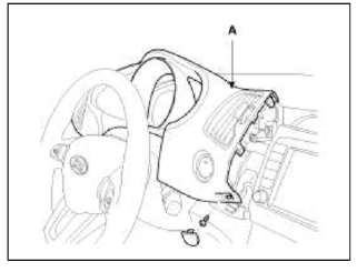
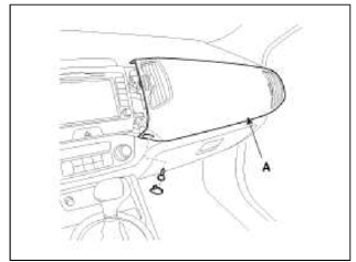
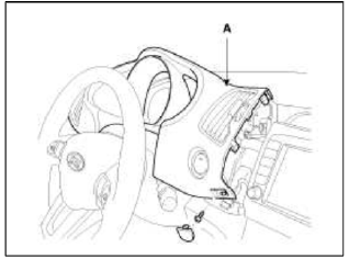
2. Using the screwdriver, remove the cluster facia panel (A).
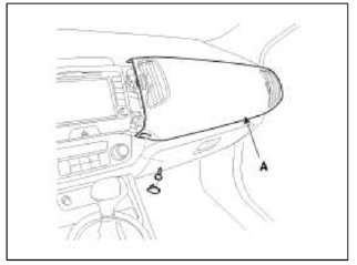
3. Using the screwdriver, remove the crash pad garnish (A).
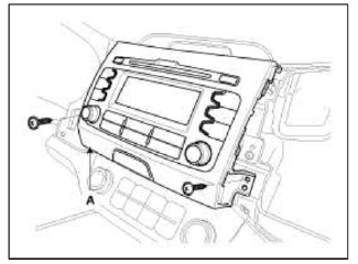
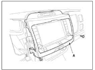
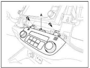
4. Using the screwdriver, remove the screws and center facia panel (A).
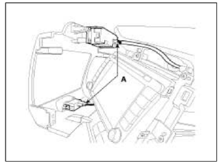
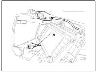
5. Disconnect the center facia connectors (A).
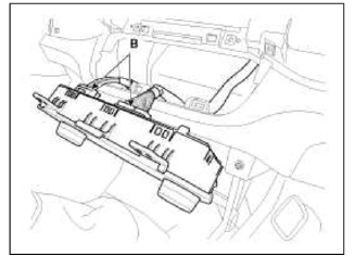
6. Loosen the control panel mounting screws and then remove the control panel (A).
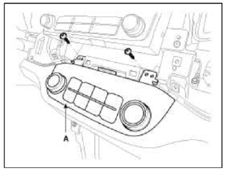
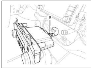
7. Disconnect the connectors and then remove the control panel (B).
8. Installation is the reverse order of removal.
Heater & A/C Control Unit (Full Automatic)
Components and Components Location
Component
Connector Pin Function
Repair procedures
Self Diagnosis
1. Self-diagnosis process
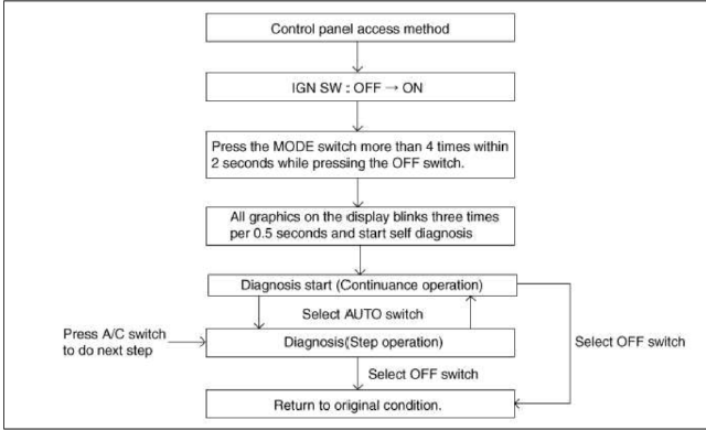
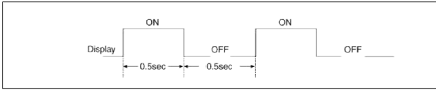
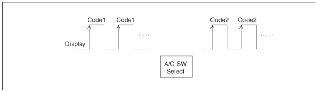
2. How to read self-diagnostic code
After the display panel flickers three tunes every 0.5 second, the corresponding fault code flickers on the setup temperature display panel every 0.5 second and will show two figures. Codes are displayed in numerical format.
Fault Code
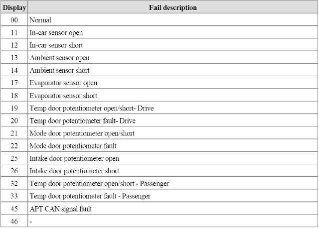
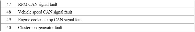
3. Fault code display
- Continuance operation : DTC code is one.
- Continuance operation : DTC code of two or more.
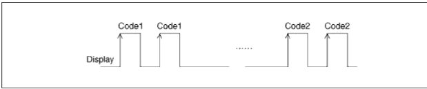
- STEP operation
4. If fault codes are displayed during the check. Inspect specific malfunctions causes by fault codes.
5. Fail safe
- In-car temperature sensor: Control with the value of 23ºC (73.4ºF)
- Ambient temperature sensor: Control with the value of 20ºC (67ºF)
- Evaporator temperature sensor: Control with the value of -2ºC (28.4ºF)
- Water temperature sensor: Control with the value of 85ºC (185ºF)
- Temperature control actuator (Air mix potentiometer): If temperature setting 17ºC-24.5ºC, fix at maximum cooling position.
If temperature setting 25ºC-32ºC, fix at maximum heating position.
- Mode control actuator (Direction potentiometer): Fix vent position, while selecting vent mode.
Fix defrost position, while selecting all except vent mode.
- Intake control actuator: Fix fresh position, while selecting fresh mode.
Fix recirculation position, while selecting recirculation mode.
Replacement
1. Disconnect the negative (-) battery terminal.
2. Using the screwdriver, remove the cluster facia panel (A).
3. Using the screwdriver, remove the crash pad garnish (A).
4. Using the screwdriver, remove the center facia panel (A).
5. Disconnect the center facia connectors (A).
6. Loosen the control panel mounting screws and then remove the control panel (A).
7. Disconnect the connectors and then remove the control panel (B).
8. Installation is the reverse order of removal.
READ NEXT:
SEE MORE:
 Defogging inside windshield
When the windshield is covered with
frost or moisture, the front view is
blurred, you should remove the frost
and moisture.
WARNING
Windshield heating
Do not use the
or
position
during cooling operation in extremely
humid weather. The difference between
the temperature of the outside ai
Explanation of scheduled maintenance items
Engine oil and filter
The engine oil and filter should be
changed at the intervals specified in the
maintenance schedule. If the vehicle is
being driven in severe conditions, more
frequent oil and filter changes are
required.
Drive belts
Inspect all drive belts for evidence of
cuts, cracks,
Content
- Home
- Kia Sportage - Fifth generation (NQ5) - (2022-2026) - Owner's Manual
- Kia Sportage - Second generation (JEKM) (2005-2015) - Body Workshop Manual
- Kia Sportage Third generation (SL) - (2011-2016) - Service and Repair Manual
- Sitemap
- Top articles
