Kia Sportage: Horn
Components and Components Location
Component Location
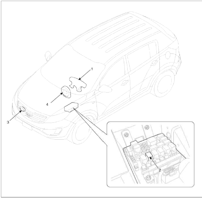
- Horn switch
- Horn relay (Engine room compartment)
- Horn (Low pitch)
- Clock spring
Repair procedures
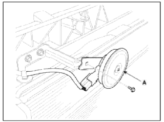
Removal
1. Remove the radiator upper cover.
(Refer to the BD group - "Front bumper")
2. Remove the bolt and disconnect the horn connector, then remove the low pitch horn (A).
Installation
1. Install the horn after connecting the horn connector.
2. Install the radiator upper cover.
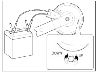
Inspection
Test the horn by connecting battery voltage to the 1 terminal and ground the 2 terminal.
The horn should make a sound. If the horn fails to make a sound, replace it.
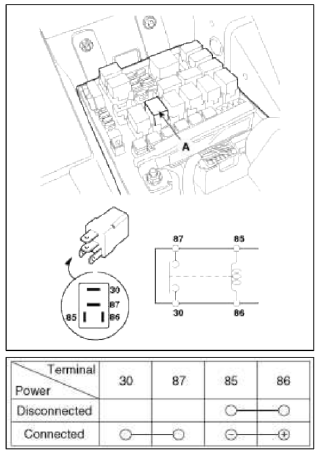
Horn Relay Inspection
1. Remove the horn relay (A) from the engine room relay box.
2. There should be continuity between the No.30 and No.87 terminals when power and ground are connected to the No.85 and No.86 terminals.
3. There should be no continuity between the No.30 and No.87 terminals when power is disconnected.
Adjustment
1. Operate the horn, and adjust the tone to a suitable level by tinning the adjusting screw.
NOTE
Horn adjustment screw is automatically sealed with silicon sealant.
The shape and size of the applied sealant is variable and tails or dribbles are acceptable and not to be tampered with.
READ NEXT:
 Specifications, Components and Components Location
Specifications
Specifications
Display System
DVD Deck
Bluetooth
Storage Memory
Components and Components Location
Component Location
AVN (A/V & Navigation) head
Description and Operation
Limitations Of The Navigation system
GPS Signal Reception State
As the GPS satellite frequency is received/transmitted in straight lines,
reception may not work if hiding devices are
placed
SEE MORE:
Installing a CRS
After selecting a proper child seat for
your child, check to make sure it fits
properly in your vehicle.
Follow the instructions provided by the
manufacturer when installing the child
seat. Note these general steps when
installing the seat to your vehicle:
Properly secure the child restr
Operating high beam
Operating high beam
To turn on the high beam headlamp:
Push the lever away from you.
The lever will return to its original
position.
The high beam indicator will light
when the headlamp high beams are
switched on.
WARNING
High beams
Do not use high beam when there are
oth
Content
- Home
- Kia Sportage - Fifth generation (NQ5) - (2022-2026) - Owner's Manual
- Kia Sportage - Second generation (JEKM) (2005-2015) - Body Workshop Manual
- Kia Sportage Third generation (SL) - (2011-2016) - Service and Repair Manual
- Sitemap
- Top articles
