Kia Sportage: Specifications, Components and Components Location
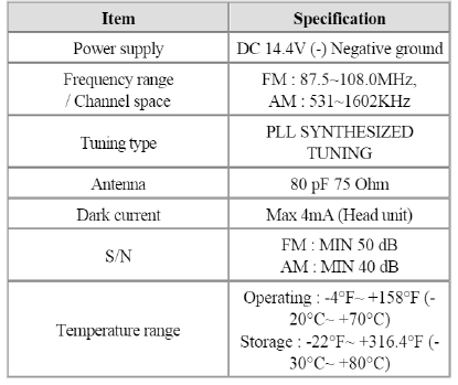
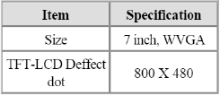
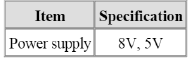
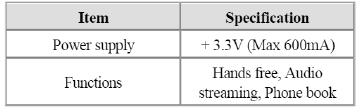
Specifications
Specifications
Display System
DVD Deck
Bluetooth
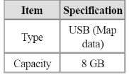
Storage Memory
Components and Components Location
Component Location
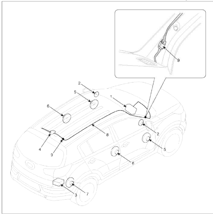
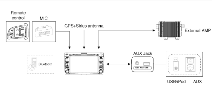
- AVN (A/V & Navigation) head unit
- Tweeter speaker
- External Amplifier
- Roof antenna (GPS + SDARS + Radio)
- Front door speaker
- Rear door speaker
- Woofer speaker
- Antenna feeder cable
- Feeder cable joint connector
SDARS : Satellite Digital Audio Radio Service
Components
AVN (A/V & Navigation) Head Unit
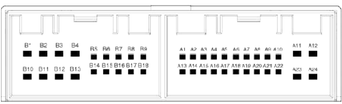
B1 -
B2 Camera video
B3 Camera GND
B4 Camera P GND
B5 SPDIF GND
B6 SPDIF +
B7 ALT_L
B8 Illumination (+)
B9 R position
B10 -
B11 Camera power
B12 Navigation voice -
B13 Navigation voice +
B14 -
B15 SPDIF -
B16 Door unlock
B11 Illumination(-)
B18 Antenna power
A1 CAN-H
A2 -
A3 -
A4 Steering remote
A5 -
A6 -
A7 AUX / iPod video
A8 AUX audio R
A9 AUX GND
A10 MIC +
A11 ACC
A12 Battery +
A13 CAN-L
A14 Auto light
A15 TGS park signal
A16 Speed
A17 Steering GND
A18 -
A19 AUX / iPod V GND
A20 AUX_Detect
A21 AUX_ Audio L
A22 MIC -
A23 Main GND
A24 Main GND
 Radio antenna
-
Signal
-
Ground
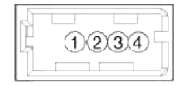 USB Connector
-
USB Ground
-
USB D (+)
-
USB D (-)
-
USB VCC
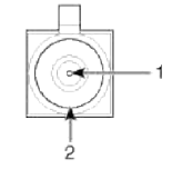 GPS Antenna
-
GPS Signal
-
Ground
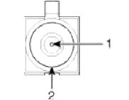 Sirius antenna
-
Sirius signal
-
Ground
[External Amplifier]
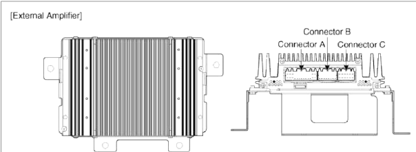
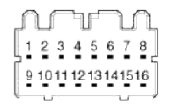
 Connector A
-
B (+)
-
B (+)
-
B (+)
-
-
-
CAN (+)
-
CAN (-)
-
ACC
-
-
-
-
-
-
-
Navigation (+)
-
Sub woofer 2 (+)
-
Sub woofer 1 (+)
-
GND
-
GND
-
GND
-
-
-
SPDIF (+)
-
SPDIF (-)
-
-
-
-
-
-
-
-
-
Navigation (-)
-
Sub woofer 2 (-)
-
Sub woofer 1 (-)
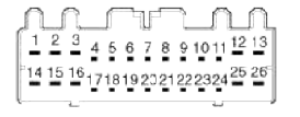
 Connector Ð’
-
-
-
-
-
-
-
-
-
-
-
-
-
-
-
-
-
-
-
-
-
-
-
-
-
-
-
-
-
-
-
-
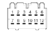 Connector C
-
Rear Door Right (+)
-
Rear Door Left (+)
-
Front Tweeter Right (+)
-
Front Tweeter Left (+)
-
Front Door Right (+)
-
Front Door Left (+)
-
Rear Door Right (-)
-
Rear Door Left (-)
-
Front Tweeter Right (-)
-
Front Tweeter Left (-)
-
Front Door Right (-)
-
Front Door Left (-)
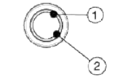
[Roof antenna (Radio + GPS + Sirius)]
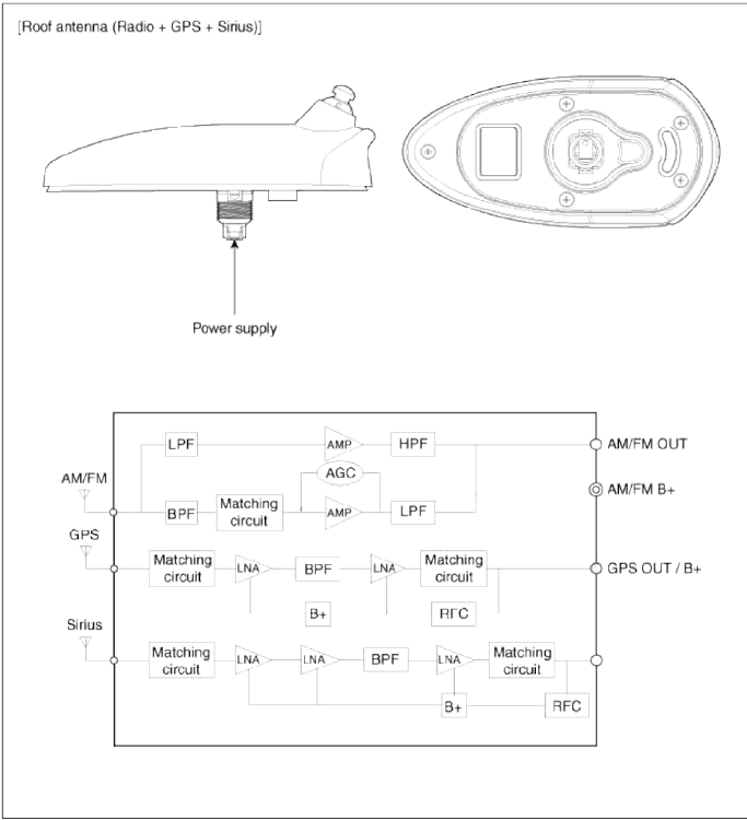
Schematic Diagrams
System Block Diagram
READ NEXT:
 Description and Operation
Limitations Of The Navigation system
GPS Signal Reception State
As the GPS satellite frequency is received/transmitted in straight lines,
reception may not work if hiding devices are
placed
Repair procedures
Removal
NOTE
Take care not to damage and scratch the hazard lamp switch assembly and
its related parts.
Apply the protective tapes to the hazard lamp switch assembly and its related
parts.
1
AUX (Auxiliary) Jack
Description and Operation
Description
The multimedia jack on the console tipper cover is for customers who like to
listen to external portable music
players like the MP3, iPod and etc., thr
SEE MORE:
Side Impact Sensor (SIS)
Description and Operation
Description
Side Impact Sensor (SIS) system consists of two P-SIS which are installed at
each center of the front door module
(LH and RH) and two SIS which are installed at each center pillar nearby (LH and
RH).
Side Pressure Sensor is also called P-SIS beca
Driver Attention Warning malfunction and limitations
Driver Attention Warning malfunction
A: Check Driver Attention Warning
(DAW) system
When Driver Attention Warning is not
working properly, the warning message
will appear and ( ) warning lights will
appear on the cluster. If this occurs, have
Driver Attention Warning inspected by
an auth
Content
- Home
- Kia Sportage - Fifth generation (NQ5) - (2022-2026) - Owner's Manual
- Kia Sportage - Second generation (JEKM) (2005-2015) - Body Workshop Manual
- Kia Sportage Third generation (SL) - (2011-2016) - Service and Repair Manual
- Sitemap
- Top articles
