Kia Sportage: Ignition System
Description and Operation
Description
Ignition timing is controlled by the electronic control ignition timing system. The standard reference ignition timing data for the engine operating conditions are preprogrammed in the memory of the ECM (Engine Control Module).
The engine operating conditions (speed, load, warm-up condition, etc.) are detected by the various sensors. Based on these sensor signals and the ignition timing data, signals to interrupt the primary current are sent to the ECM. The ignition coil is activated, and timing is controlled.
Repair procedures
On-vehicle Inspection
Spark Test
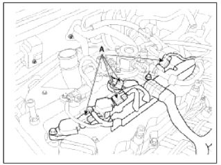
1. Disconnect the ignition coil connectors (A).
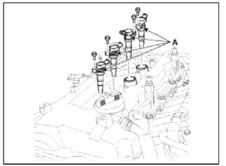
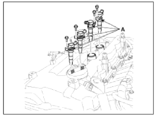
2. Remove the ignition coils (A).
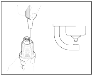
3. Using a spark plug socket, remove the spark plug.
4. Install the spark plug to the ignition coil.
5. Ground the spark plug to the engine.
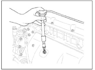
6. Check if spark occurs while engine is being cranked.
NOTE
To prevent fuel being injected from injectors while the engine is being cranked, disconnect the injector connector.
Crank the engine for no more than 5 ~ 10 seconds.
7. Inspect all the spark plugs.
8. Using a spark plug socket, install the spark plug.
9. Install the ignition coil.
10. Reconnect the ignition coil connector
Inspect Spark Plug
1. Disconnect the ignition coil connectors (A).
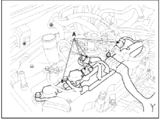
2. Remove the ignition coils (A).
3. Using a spark plug socket, remove the spark plug.
CAUTION
Be careful that no contaminates enter through the spark plug holes.
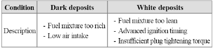
4. Inspect the electrodes (A) and ceramic insulator (B).
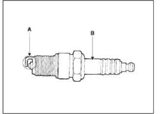
Inspection Of Electrodes
5. Check the electrode gap (A).
Standard
Unleaded : 1.0 ~ 1.1 mm (0.0394 ~ 0.0433 in.)
Inspection Ignition Coil
1. Measure the primary coil resistance between terminals (+) and (-).
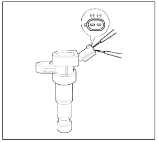
Standard value: 0.62Ω +- 10%
Removal and Installation
1. Disconnect the ignition coil connectors (A).
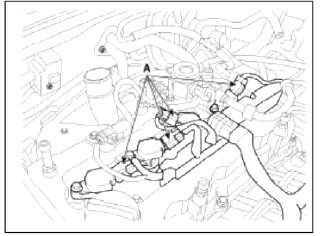
2. Remove the ignition coils (A).
Tightening torque: 3.9 ~ 5.9N.m (0.4 ~ 0.6kgf.m, 2.9 ~ 4.3lb-ft)

3. Installation is the reverse of removal.
READ NEXT:
 Description and Operation | Repair procedures
Description
The charging system includes a battery, an alternator with a built-in regulator, and the charging indicator light and wire.
The Alternator has built-in diodes, each rectifying AC
SEE MORE:
Schematic Diagrams, Description and Operation
Schematic Diagrams
System Block Diagram
Component Parts And Function Outline
* ETS : Electronic Throttle System
Description and Operation
Cruise Control
The cruise control system is engaged by the cruise "ON/OFF" main switch
located on right of steering wheel
colum
Blind-Spot Collision-Avoidance Assist settings
Setting features
Blind-Spot Safety
Driver Assistance
Blind-Spot Safety
Active Assist
Warning Only
Off
With the engine on, select or deselect
Settings?Driver Assistance ? Blind-
Spot Safety the User Settings menu or
select or deselect Settings? Vehicle ?
Driver Assistance
Content
- Home
- Kia Sportage - Fifth generation (NQ5) - (2022-2026) - Owner's Manual
- Kia Sportage - Second generation (JEKM) (2005-2015) - Body Workshop Manual
- Kia Sportage Third generation (SL) - (2011-2016) - Service and Repair Manual
- Sitemap
- Top articles
