Kia Sportage: Schematic Diagrams, Repair procedures | Positive Crankcase Ventilation (PCV) Valve
Schematic Diagrams
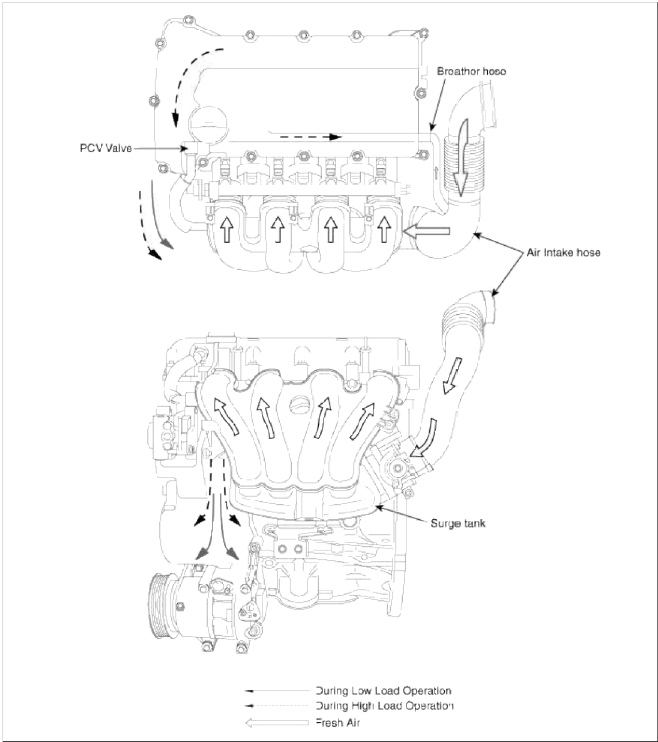
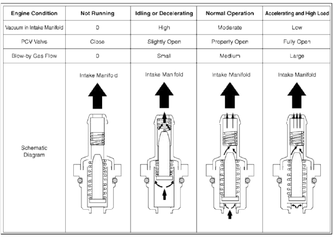
Schematic Diagram
Repair procedures
Inspection
1. After disconnecting the vapor hose from the PCV valve, remove the PCV valve.
2. Reconnect the PCV valve to the vapor hose.
3. Run the engine at idle, then put a finger over the open end of the PCV valve and make sure that intake manifold vacuum can be felt.
NOTE
The plunger inside the PCV valve will move back and forth at vacuum.
4. If the vacuum is not felt inspect PCV operation, if operating correctly clean or replace the vapor hose.
Positive Crankcase Ventilation (PCV) Valve
Description and Operation
Operation Principle
Repair procedures
Removal
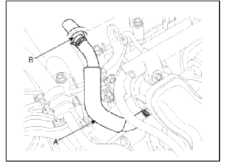
1. Disconnect the vapor hose (A).
2. Remove the PCV valve (B).
Inspection
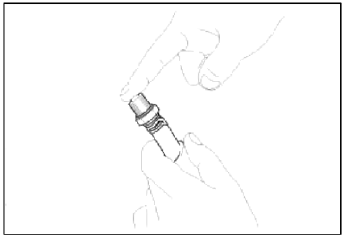
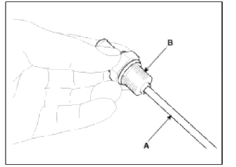
1. Insert a thin stick (A) into the PCV valve (B) from the threaded side to check that the plunger movement.
NOTE
If the plunger does not move (PCV valve is clogged), clean or replace the valve.
Installation
1. Installation is reverse of removal.
PCV Valve installation:
1.9 ~ 2.8 N.m (0.19 ~ 0.29 kgf.m, 1.4 ~ 2.1 lb-ft)
READ NEXT:
 Description and Operation, Schematic Diagrams
Description and Operation
Description
The Evaporative Emission Control System prevents fuel vapor stored in fuel
tank from vaporizing into the
atmosphere. When the fuel evaporates in the fu
SEE MORE:
Underdrive Brake Control Solenoid Valve (UD/B_VFS) | Overdrive Clutch Control Solenoid Valve (OD/C_VFS)
Description and Operation
Description
Underdrive brake control solenoid valve (UD/B_VFS) is attached to the valve body. This variable force solenoid valve directly controls the hydraulic pressure inside the underdrive brake.
Specifications
Specifications
Direct control VFS [35R/C
Specifications, Schematic Diagrams, Description and Operation
Specifications
Specifications
Electrical Performance
Schematic Diagrams
Circuit Diagram
Description and Operation
Description
Body control module receives various input switch
signals controlling time and alarm functions for front
washer interlocking wiper, front int
Content
- Home
- Kia Sportage - Fifth generation (NQ5) - (2022-2026) - Owner's Manual
- Kia Sportage - Second generation (JEKM) (2005-2015) - Body Workshop Manual
- Kia Sportage Third generation (SL) - (2011-2016) - Service and Repair Manual
- Sitemap
- Top articles
