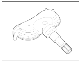
Kia Sportage: TPMS Sensor
Description and Operation
Description
1. Mode
- Configuration State
- All sensors should be in the Low Line (Base) state.
- In Low Line (Base) configuration, sensor transmissions occur every 3 minutes 20 seconds (nominal) and pressure is measured every 20 seconds.
- Normal Fixed Base State
- Sensor transmissions continue at the Low Line (Base) configuration defined rates until the state is either changed by LF command or by the sensor detecting a condition that requires a temporary change to another state.
- The LF command to this state must contain the sensors ID.
- Storage Auto State:
- This state is a Low current consumption state.
- Sensors are in this state when they first arrive at the dealership (either on the vehicle or as replacement spares).
- In this state, the sensor does not measure pressure / temperature / battery level.
- The sensor will not transmit in this state unless requested to do so by the initiate command.
- Alert State:
- The sensor automatically enters this state if the measured temperature exceeds 230 ºF(110 ºС) and over temperature shutdown is likely.
- In this state, pressure is measured every 4 seconds and RF data transmitted every 4 seconds.
- The state lasts for 1 minute if it is pressure triggered.
- This state is also entered when a 3 psi change in pressure from the last RF transmission occurs.
NOTE
Sensor mode is used to configure sensor between high line and low line system. TPM sensor for SL should be set to low line.
Repair procedures
Removal
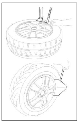
Tire Removal
1. Deflate file & remove balance weights.
NOTE
Sensor can be unscrewed before unseating the the bead.
CAUTION
- The tire bead should be broken approx. 90º from the valve side of the wheel. The bead breaker should not be set too deep.
- Avoid tire/tool contact with the valve on dismount.
- Dismount should end near the valve.
Sensor Removal
CAUTION
Handle the sensor with care.
1. Remove the valve nut.
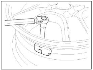
CAUTION
The valve nut should not be re-used.
2. Discard the valve assembly.
Installation
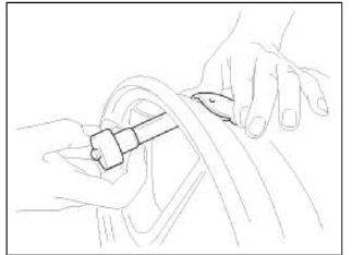
Sensor Fit
CAUTION
- Handle the sensor with care.
- Avoid lubricant contact.
- Ensure that the wheel to be fitted is designed for sensor mount. There should normally be a mark to indicate this.
- Ensure that the valve hole and mating face of the wheel are clean.
1. Slide the sensor-valve unit through the valve hole of the rim. Hold the sensor against the rim and the rubber grommet against the sealing surface.
2. Insert the nut over the valve stem and then tighten the nut.
3. Continue to tightening the nut until contact with the rim and then tighten to 3.5 ~ 4.5Nm.
CAUTION
- Tighten slowly with quarter turn steps until the final torque is reached.
- Do not exceed allowed torque.
- Do not use electric or pneumatic tools.
4. Check that the sensor is firmly attached to the rim.
CAUTION
Risk of damage during the tire installation/removal if the sensor is not firmly attached to the rim.
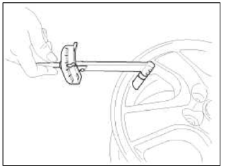
5. Carry out inflation / pressure correction and then fit valve cap.
CAUTION
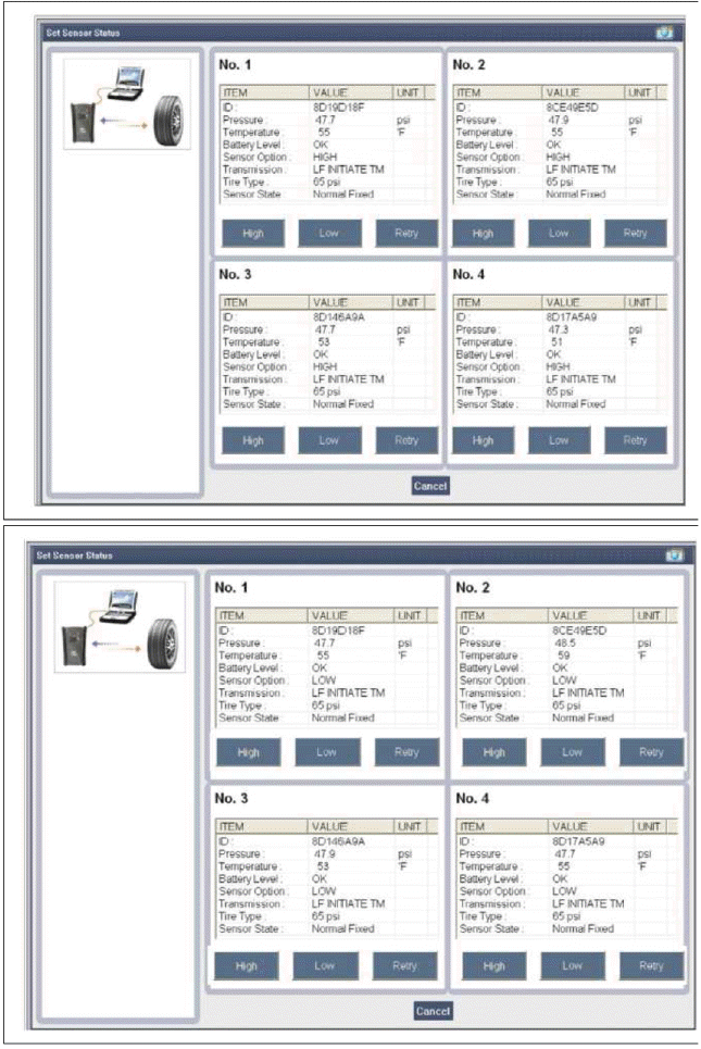
Change the newly installed sensor mode to Normal Fixed Base (Low Line) with the 'GDS'.
Mode (Status / option) of the sensor installed to the vehicle should be Normal Fixed Base (Low).
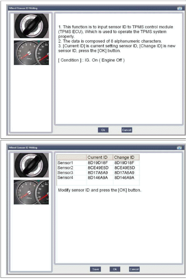
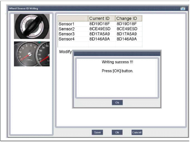
Set Sensor Status
Sensor ID Writing (Wireless)
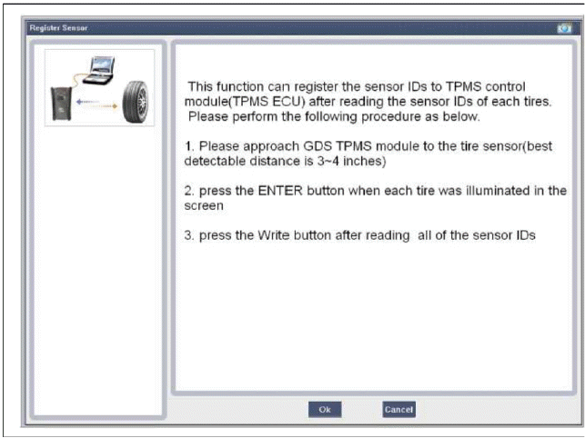
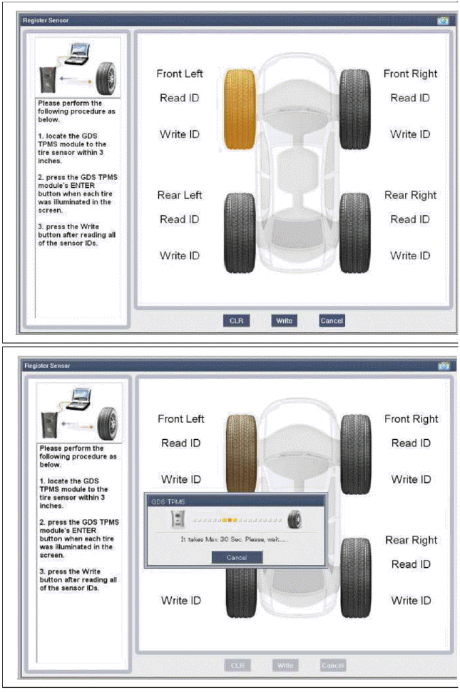
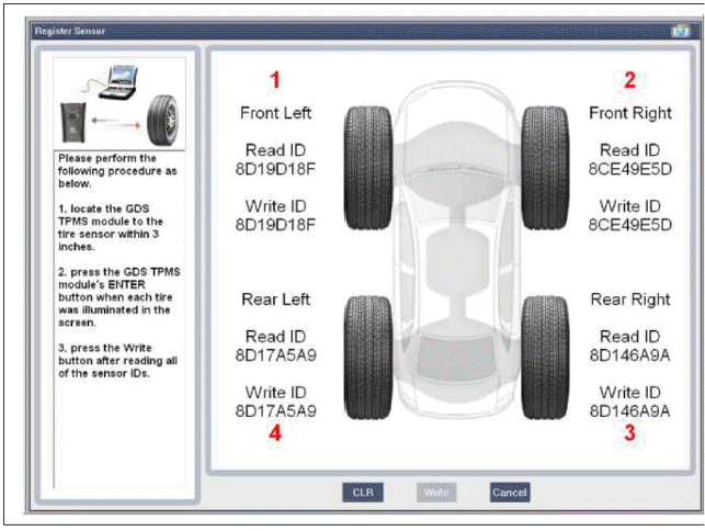
Sensor ID Writing
READ NEXT:
 TPMS Receiver
Components and
Components Location
Components
TPMS Receiver Circuit Diagram
Harness Connector
Battery
CAN_High
GND
-
-
-
IGN
CAN_Low
-
-
-
-
Description and
SEE MORE:
Troubleshooting
Basic Troubleshooting
Basic Troubleshooting Guide
Customer Problem Analysis Sheet
Basic Inspection Procedure
Measuring Condition of Electronic Pails' Resistance
The measured resistance at high temperature after vehicle running may be high
or low. So all resistance must be
measu
Front Door
Components and Components Location
Components
Front door trim
Front door inside handle cap
Front door trim seal
Front door quadrant inner cover
Front door module
Front door panel
Front door belt outside molding
Front door body side
weatherstrip
Front door side weathers
Content
- Home
- Kia Sportage - Fifth generation (NQ5) - (2022-2026) - Owner's Manual
- Kia Sportage - Second generation (JEKM) (2005-2015) - Body Workshop Manual
- Kia Sportage Third generation (SL) - (2011-2016) - Service and Repair Manual
- Sitemap
- Top articles
