Kia Sportage: Troubleshooting
Basic Troubleshooting
Basic Troubleshooting Guide
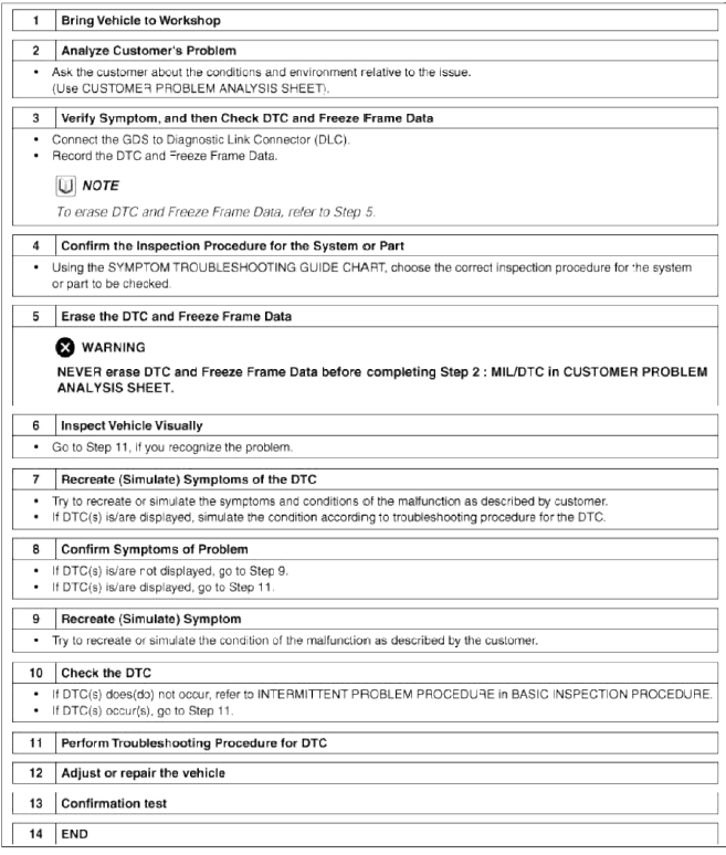
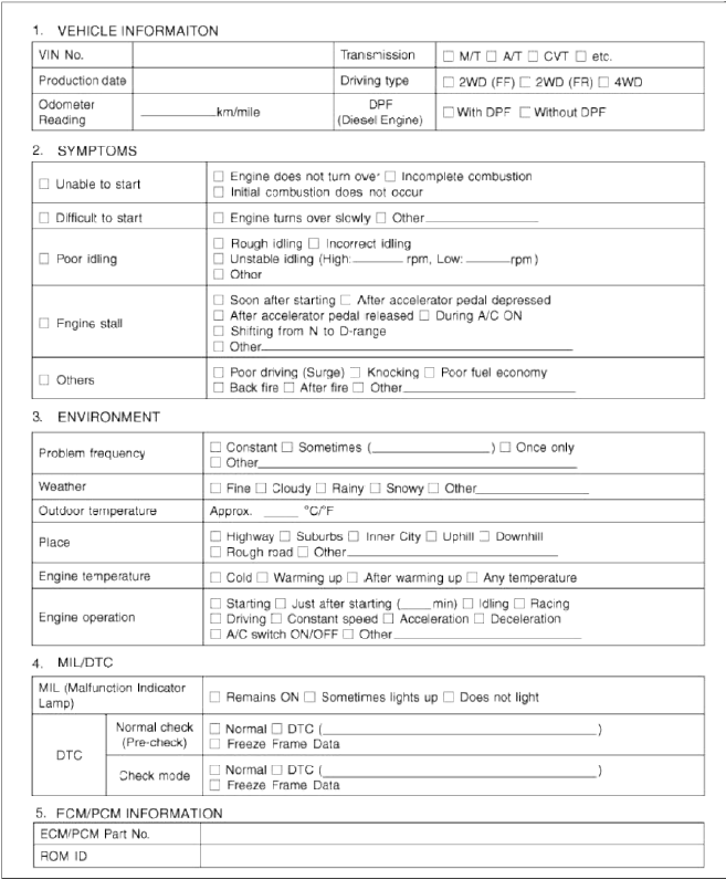
Customer Problem Analysis Sheet
Basic Inspection Procedure
Measuring Condition of Electronic Pails' Resistance
The measured resistance at high temperature after vehicle running may be high or low. So all resistance must be measured at ambient temperature (20ºC, 68ºF), unless stated otherwise.
NOTE
The measured resistance in except for ambient temperature (20ºC, 68ºF) is reference value.
Intermittent Problem Inspection Procedure
Sometimes the most difficult case in troubleshooting is when a problem symptom occurs but does not occur again during testing. An example would be if a problem appears only when the vehicle is cold but has not appeared when warm. In this case, the technician should thoroughly make out a "Customer Problem Analysis Sheet" and recreate (simulate) the environment and condition which occurred when the vehicle was having the issue.
1. Clear Diagnostic Trouble Code (DTC).
2. Inspect connector connection, and check terminal for poor connections, loose wires, bent, broken or corroded pins, and then verify that the connectors are always securely fastened.
3. Slightly shake the connector and wiring harness vertically and horizontally.
4. Repair or replace the component that has a problem.
5. Verify that the problem has disappear ed with the road test.
- Simulating Vibration
- Sensors and Actuators : Slightly vibrate sensors, actuators or relays with finger.
WARNING
Strong vibration may break sensors, actuators or relays.
- Connectors and Harness : Lightly shake the connector and wiring harness vertically and then horizontally.
- Simulating Heat
- Heat components suspected of causing the malfunction with a hair dryer or other heat source.
WARNING
- DO NOT heat components to the point where they may be damaged.
- DO NOT heat the ECM directly.
- Simulating Water Sprinkling
- Sprinkle water onto vehicle to simulate a rainy day or a high humidity condition.
WARNING
DO NOT sprinkle water directly into the engine compartment or electronic components.
- Simulating Electrical Load
- Turn on all electrical systems to simulate excessive electrical loads (Radios, fans, lights, rear window defogger, etc.).
Connector Inspection Procedure
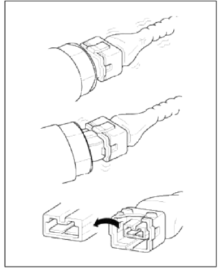
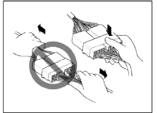
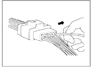
1. Handling of Connector
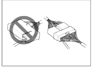
- Never pull on the wiring harness when disconnecting connectors.
- When removing the connector with a lock, press or pull locking lever.
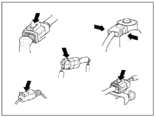
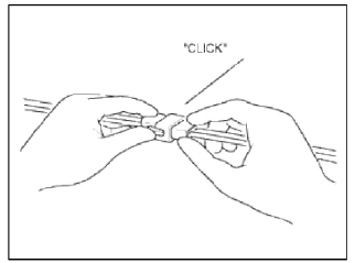
- Listen for a click when locking connectors. This sound indicates that they are securely locked.
- When a tester is used to check for continuity, or to measure voltage, always insert tester probe from wire harness side.
- Check waterproof connector terminals from the connector side. Waterproof connectors cannot be accessed from harness side.
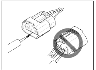
NOTE
- Use a fine wire to prevent damage to the terminal.
- Do not damage the terminal when inserting the tester lead.
2. Checking Point for Connector
- While the connector is connected: Hold the connector, check connecting condition and locking efficiency.
- When the connector is disconnected:
Check missed terminal, crimped terminal or broken core wire by slightly
pulling the wire harness.
Visually check for rust, contamination, defamation and bend.
- Check terminal tightening condition: Insert a spare male terminal into a female terminal, and then check terminal tightening conditions.
- Pull lightly on individual wires to ensure that each wire is seemed in the terminal.
3. Repair Method of Connector Terminal
- Clean the contact points using air gun and/or shop rag.
NOTE
Never use sand paper when polishing the contact points, otherwise the contact point may be damaged.
- In case of abnormal contact pressure, replace the female terminal.
Wire Harness Inspection Procedure
1. Before removing the wire harness, check the wire harness position and crimping in order to restore it correctly.
2. Check whether the wire harness is twisted, pulled or loosened.
3. Check whether the temperature of the wire harness is abnormally high.
4. Check whether the wire harness is rotating, moving or vibrating against the sharp edge of a part.
5. Check the connection between the wire harness and any installed part.
6. If the covering of wire harness is damaged; secure, repair or replace the harness.
Electrical Circuit Inspection Procedure
- Check Open Circuit
1. Procedures for Open Circuit
- Continuity Check
- Voltage Check
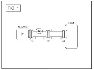
If an open circuit occurs (as seen in [FIG. 1] ), it can be found by performing Step 2 (Continuity Check Method) or Step 3 (Voltage Check Method) as shown below.
2. Continuity Check Method
NOTE
When measuring for resistance, lightly shake the wire harness above and below or from side to side.
Specification (Resistance)
1Ω or less →Normal Circuit
1MΩ or Higher → Open Circuit
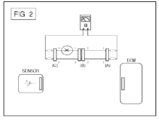
- Disconnect connectors (A), (C) and measure resistance between connector
(A) and (C) as shown in [FIG.2].
In [FIG.2.] the measured resistance of line 1 and 2 is higher than 1MΩ and below 1Ω respectively.
Specifically the open circuit is line 1 (Line 2 is normal). To find exact break point, check sub line of line 1 as described in next step.
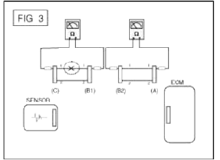
- Disconnect connector (B), and measure for resistance between connector
(C) and (B1) and between (B2)
and (A) as shown in [FIG. 3].
In tills case the measured resistance between connector (C) and (В 1) is higher than 1MΩ and the open circuit is between terminal 1 of connector (C) and terminal 1 of connector (B1).
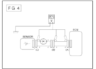
3. Voltage Short Method
- With each connector still connected, measure the voltage between the
chassis ground and terminal 1 of each
connectors (A), (B) and (C) as shown in [FIG. 4].
The measured voltage of each connector is 5V, 5V and 0V respectively. So the open circuit is between connector (C) and (B).
- Check Short Circuit
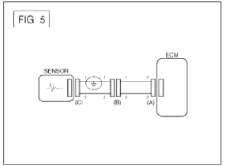
1. Test Method for Short to Ground Circuit
- Continuity Check with Chassis Ground
If short to ground circuit occurs as shown in [FIG. 5], the broken point can be found by performing Step 2 (Continuity Check Method with Chassis Ground) as shown below.
2. Continuity Check Method (with Chassis Ground)
NOTE
Lightly shake the wire harness above and below, or from side to side when measuring the resistance.
Specification (Resistance)
1Ω or less → Short to Ground Circuit
1MΩ or Higher → Normal Circuit
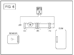
- Disconnect connectors (A), (C) and measure for resistance between
connector (A) and Chassis Ground as
shown in [FIG. 6].
The measured resistance of line 1 and 2 in this example is below 1Ω and higher than 1MΩ respectively.
Specifically the short to ground circuit is line 1 (Line 2 is normal). To find exact broken point, check the sub line of line 1 as described in the following step.
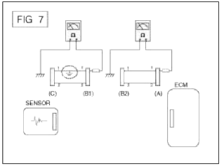
- Disconnect connector (B), and measure the resistance between connector
(A) and chassis ground, and
between (B1) and chassis ground as shown in [FIG. 7].
The measured resistance between connector (B1) and chassis ground is 1Ω or less. The short to ground circuit is between terminal 1 of connector (C) and terminal 1 of connector (B1).
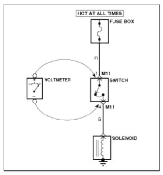
- Testing For Voltage Drop
This test checks for voltage drop along a wire, or through a connection or switch.
- Connect the positive lead of a voltmeter to the end of the wire (or to the side of the connector or switch) closest to the battery.
- Connect the negative lead to the other end of the wire, (or the other side of the connector or switch)
- Operate the circuit.
- The voltmeter will show the difference in voltage between the two points. A difference, or drop of more than 0.1 volts (50mV in 5V circuits), may indicate a problem. Check the circuit for loose or dirty connections.
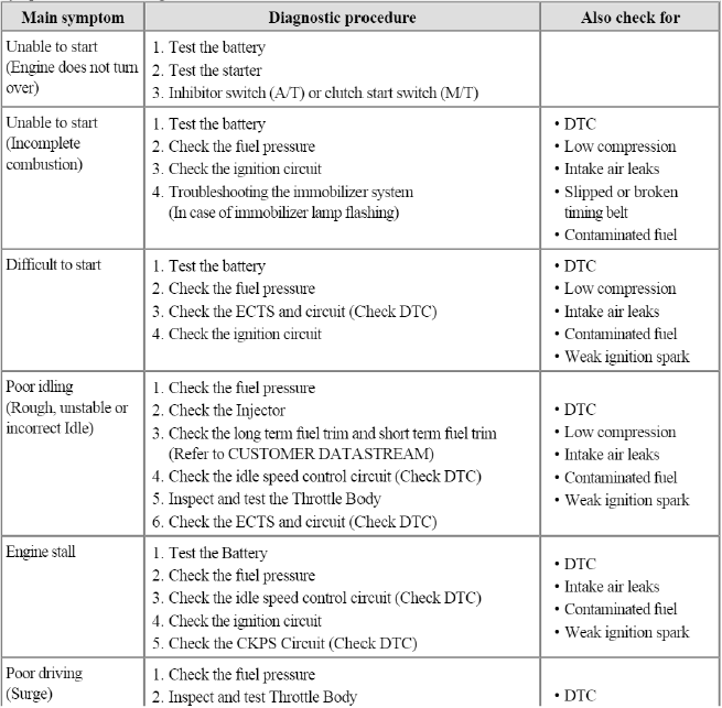
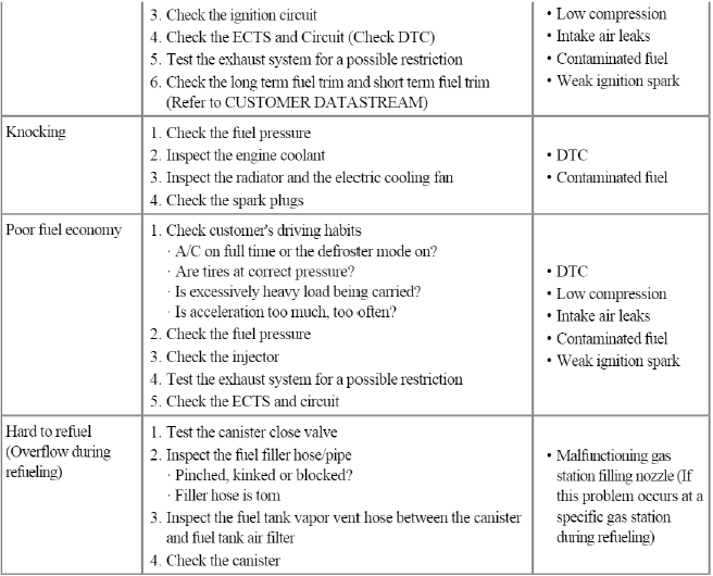
Symptom Troubleshooting Guide Chart
READ NEXT:
 Description and Operation
OBD-II review
1. Overview
The California Air Resources Board (CARB) began regulation of On Board
Diagnostics (OBD) for vehicles sold in
California beginning with the 1988 model year. The fi
Components and Components Location
Components Location
Engine Control Module (ECM)
Manifold Absolute Pressure Sensor (MAPS) #1
Intake Air Temperature Sensor (IATS)
Manifold Absolute Pressure Sensor (MAPS) #2
Engine
SEE MORE:
Components and Components Location | Repair procedures
Components (1)
Brake booster
Master cylinder assembly
O-ring
Components (2)
[2.0T - GDI ENGINE ONLY]
Vacuum pump
Bracket
Repair procedures
Brake Booster Operating Test
For simple checking of the brake booster operation, carry out the foll
Surround View Monitor operation
Parking/View button
Press the Parking/View button (1) to turn
on or off Surround View Monitor.
Front view
Front view function is displayed on the
screen when the gear is in N (Neutral) or
D (Drive) to assist in parking. The front
view has a top view, front view, side view
and 3D view.
Content
- Home
- Kia Sportage - Fifth generation (NQ5) - (2022-2026) - Owner's Manual
- Kia Sportage - Second generation (JEKM) (2005-2015) - Body Workshop Manual
- Kia Sportage Third generation (SL) - (2011-2016) - Service and Repair Manual
- Sitemap
- Top articles
