Kia Sportage: Antenna | Audio Remote Control
Repair procedures
Inspection
Antenna Cable
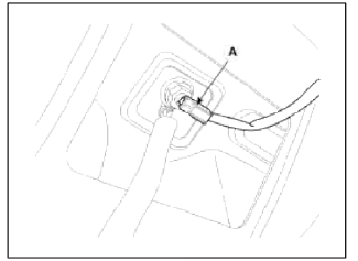
1. Remove the antenna jack from the audio unit and antenna.
2. Check for continuity between the center poles of antenna cable.
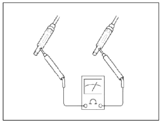
3. Check for continuity between the outer poles of antenna cable. There should be continuity.
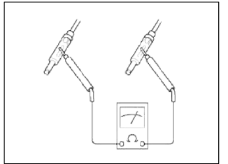
4. If there is no continuity, replace the antenna cable.
5. Check for continuity between the center pole (A) and outer pole (B) of antenna cable. There should be no continuity.
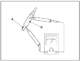
6. If there is continuity, replace the antenna cable.
Removal
Roof Antenna
1. Remove the rear roof trim.
(Refer to the BD group - "Roof trim")
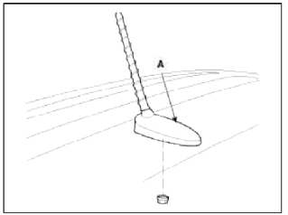
2. Disconnect the roof antenna feeder cable and connector (A) from the roof antenna.
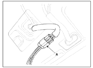
3. Disconnect the antenna power cable (A).
4. Remove the roof antenna (A) after removing a nut.
Installation
1. Install the roof antenna to the roof panel.
Tightening torque (nut): 8 ~ 15 N.m (0.8 ~ 1.5 kgf.m, 5.8 ~ 10.8 lb-ft)
2. Connect the feeder cable to the antenna.
3. Connect the power cable to the antenna.
4. Install the rear roof trim.
NOTE
- Make sure that the cables and connectors are plugged in properly.
- Check the audio system.
Audio Remote Control
Components and Components Location
Component Location
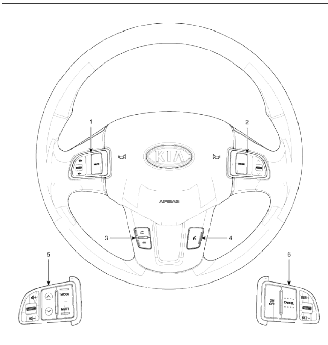
- Audio remote control switch (Left)
- Audio remote control switch (Right)
- Bluetooth switch
- Voice switch
- Audio remote control switch
- Cruise remote control switch
Schematic Diagrams
Circuit Diagram
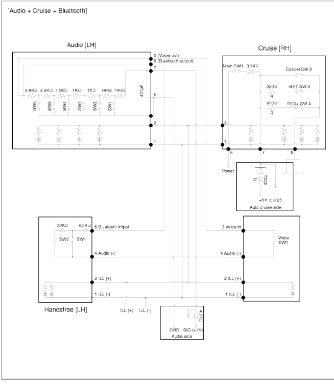
[Audio + Cruise]
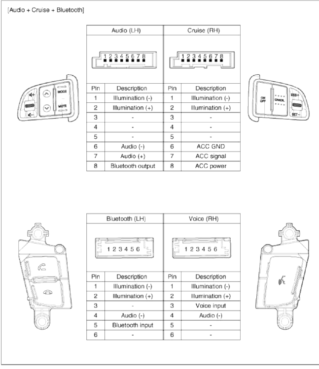
![[Audio + Cruise + Bluetooth]](images/books/1921/7/index%2035.png)
[Audio + Cruise + Bluetooth]
Repair procedures
Inspection
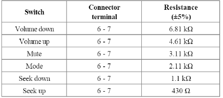
1. Check for resistance between No.6 and No.7 terminals in each switch position.
![[Audio System]](images/books/1921/7/index%2038.png)
[Audio System]
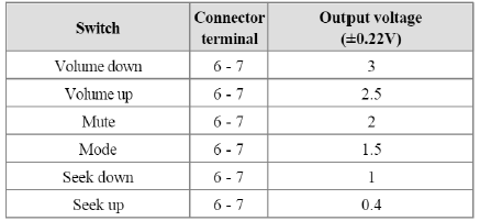
2. Check for voltage between No.6 and No.7 terminal in each switch position.
[Audio System]
Removal
1. Remove the driver airbag module.
(Refer to the RT group - "Airbag module")
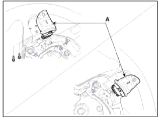
2. Remove the steering wheel remote control switch mounting screws (2EA).
Disconnect the connector and remove the steering wheel remote control switch (A).
Installation
1. Install the audio remote control switch on the steering wheel.
2. Reconnect the audio remote control switch connector and airbag connectors.
NOTE
Make sure that the switch connector is plugged in properly.
3. Install the driver airbag module.
NOTE
Turn the ignition switch ON; the SRS indicator light should be turned on for about six seconds and then go off.
Make sure horn button works.
READ NEXT:
 AUX (Auxiliary) Jack | Troubleshooting
Schematic Diagrams
Circuit Diagram
[AUX, USB, iPod Jack]
Description and Operation
Description
The AUX, iPod and USB JACK on the center console is for customers who like to listen
SEE MORE:
Starter Relay
Repair procedures
Inspection
1. Remove the fuse box cover.
2. Remove the starter relay (A).
3. Using an ohmmeter, check that there is continuity between each terminal.
4. Apply 12V to terminal 85 and ground to terminal 86.
Check for continuity between terminals 30 and 87.
5. If ther
Power Door Mirrors
Components and Components Location
Component Location
Power door mirror
Power door mirror
switch
Power Door Mirror Switch
Schematic Diagrams
Circuit Diagram
Connector A
-
-
-
Battery
GND
ACC
-
Driver door mirror motor (vertical)
Driver door mirr
Content
- Home
- Kia Sportage - Fifth generation (NQ5) - (2022-2026) - Owner's Manual
- Kia Sportage - Second generation (JEKM) (2005-2015) - Body Workshop Manual
- Kia Sportage Third generation (SL) - (2011-2016) - Service and Repair Manual
- Sitemap
- Top articles
