Kia Sportage: AUX (Auxiliary) Jack | Troubleshooting
Schematic Diagrams
Circuit Diagram
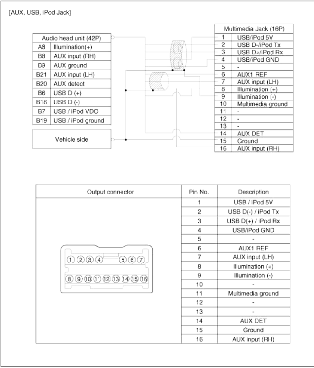
[AUX, USB, iPod Jack]
Description and Operation
Description
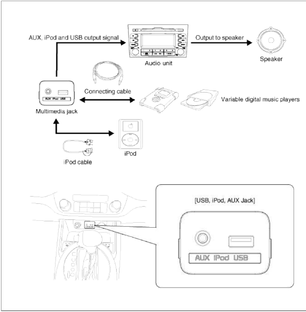
The AUX, iPod and USB JACK on the center console is for customers who like to listen to external portable music players like the MP3, iPod, earphone, USB memory stick, CD player and etc., through the vehicle's sound system when it is linked to this jack. The customer has this added option.
In case of distortions from media connected to the AUX source, the audio unit may not be defective but the output level of the used media does not match the specification of the AUX input.
Repair procedures
Removal
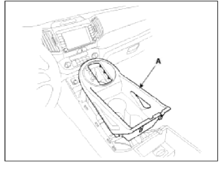
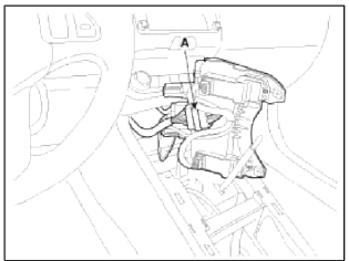
1. Remove the knob. Remove the floor console upper cover (A) using the appropriate tool.
(Refer to the BD group - "Console")
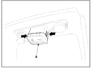
2. Loosen screws (2EA) and remove the floor console tray (A).
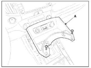
NOTE
Take care not to damage the hook when removing the switch.
3. Disconnect the connectors (A) from the floor console tray.
4. Remove the multimedia jack (A) from the floor console tray after pressing the hooks.
Installation
1. Install the multimedia jack.
2. Install the floor console tray.
3. Install the floor console upper cover.
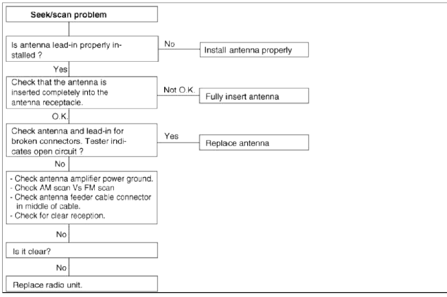
Troubleshooting
Troubleshooting
Customer Complaint Analysis Check Sheet
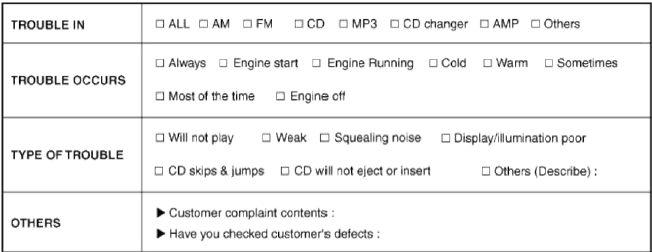
* Using the customer complaint analysis check sheet for reference, ask the customer for as much detail as possible about the problem.
There are six areas where a problem can occur: wiring harness, the radio, the CD player, and speaker.
Troubleshooting enables you to confine the problem to a particular area.
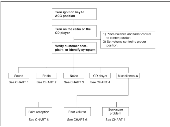
Chart 1
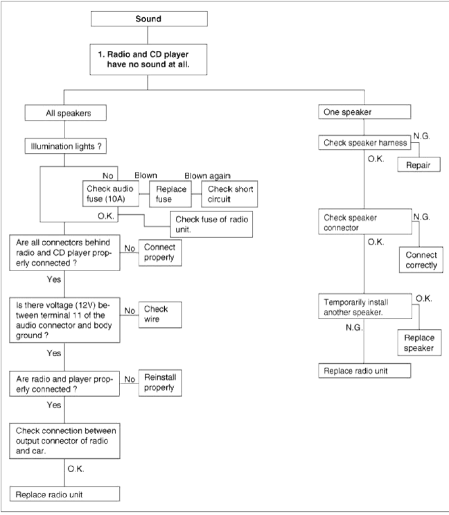
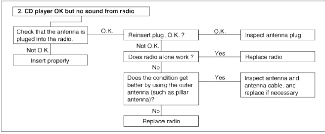
Chart 2
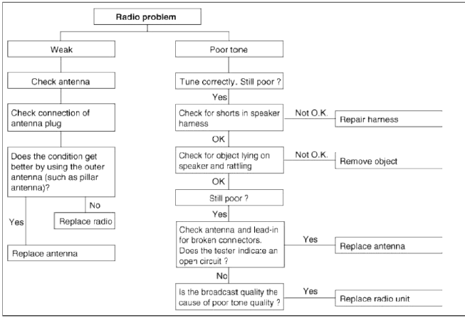
Chart 3
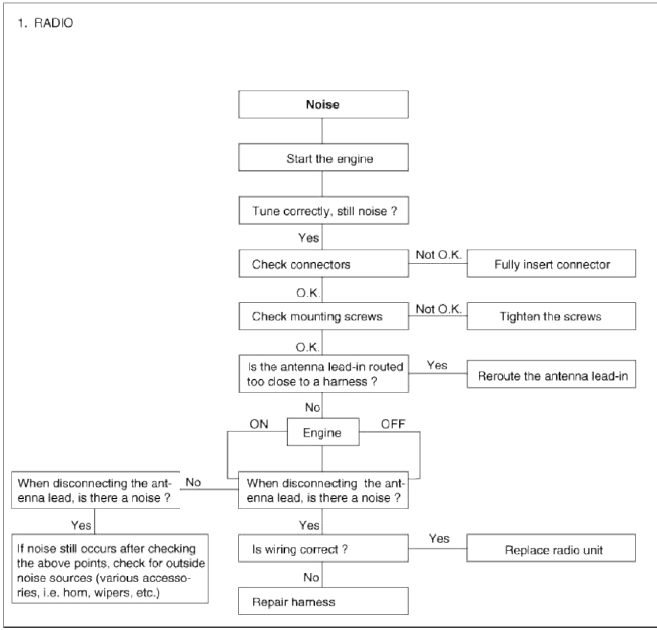
Chart 4
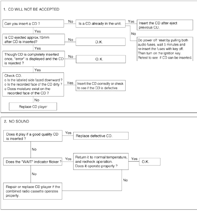
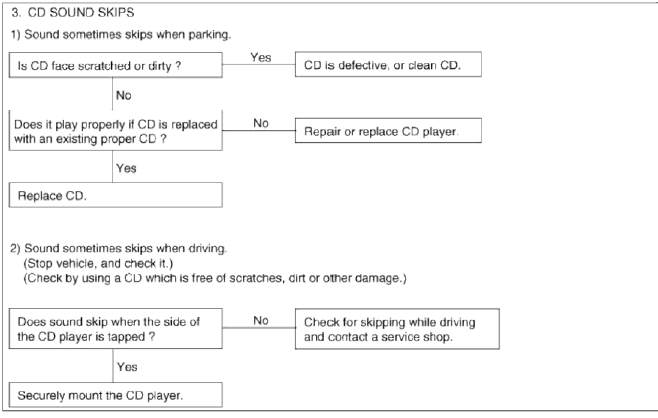
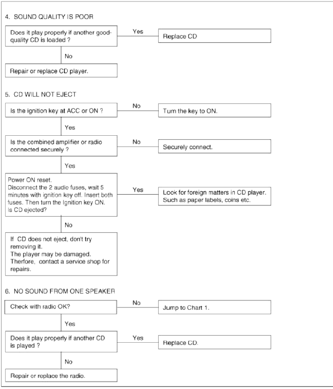
Chart 5
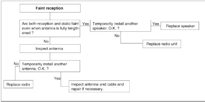
Chart 6
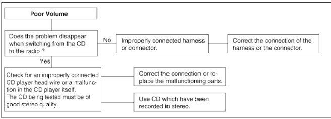
Chart 7
READ NEXT:
 Specifications, Components and Components Location | Repair procedures
Specifications
Specifications
Components and Components Location
Component (1)
<Installation order: A→B→C→D>
Steering column shaft
Lighting switch
SEE MORE:
General Information
Specifications
Specifications
NOTE
O.D. : Outer Diameter
I.D. : Inner Diameter
Specification (ESC)
Service Standard
Tightening Torques
Lubricants
Special Service Tools
Special Service Tools
Troubleshooting
Troubleshooting
Problem Symptoms Table
Use the t
Body modification tools
Modification tools
Cut and disassembly tools
Assembly tools
Measurement tools
Welding machine
Buffing and grinding tools
Handheld tools
Repair tools set
Content
- Home
- Kia Sportage - Fifth generation (NQ5) - (2022-2026) - Owner's Manual
- Kia Sportage - Second generation (JEKM) (2005-2015) - Body Workshop Manual
- Kia Sportage Third generation (SL) - (2011-2016) - Service and Repair Manual
- Sitemap
- Top articles
