Kia Sportage: AUX (Auxiliary) Jack
Description and Operation
Description
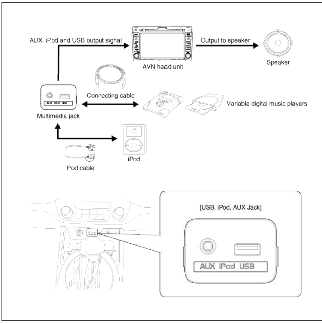
The multimedia jack on the console tipper cover is for customers who like to listen to external portable music players like the MP3, iPod and etc., through the vehicle's sound system when it is linked to this jack. The customer has this added option.
In case of distortions from media connected to the AUX source, the audio unit may not be defective but the output level of the used media does not match the specification of the AUX input.
Schematic Diagrams
Circuit Diagram
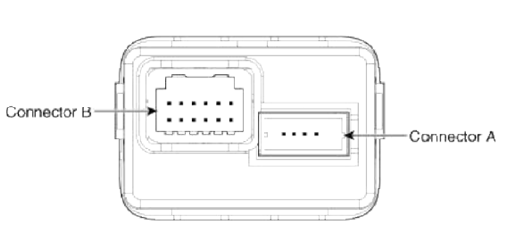
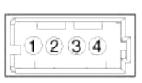 Connector A
- USB VOD
- USB D (-)
- USB D (+)
- USB Ground
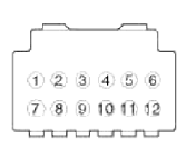 Connector Ð’
- AUX Input (LH)
- AUX Input (RH)
- AUX Detect
- AUX Video input
- -
- Illumination (+)
- AUX REF
- -
- -
- AUX V Ground
- Illumination (-)
- Ground
Repair procedures
Removal
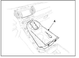
1. Remove the knob. Remove the floor console upper cover (A) using the appropriate tool.
(Refer to the BD group - "Console")
2. Loosen screws (2EA) and remove the floor console tray (A).
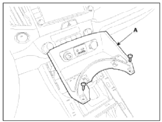
NOTE
Take care not to damage the hook when removing the switch.
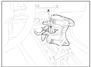
3. Disconnect the connectors (A) from the floor console tray.
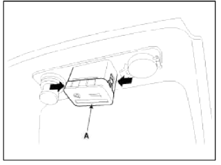
4. Remove the multimedia jack (A) from the floor console tray after pressing the hooks.
Installation
1. Install the multimedia jack.
2. Install the floor console tray.
3. Install the floor console upper cover.
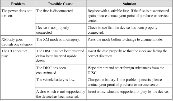
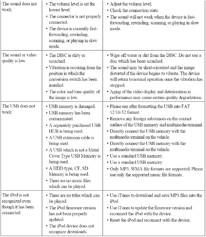
Troubleshooting
Troubleshooting Guide
Before Thinking The Product Has Malfunctioned
1. Errors which occur during the operation or installation of the device may be mistaken as a malfunction of the actual device.
2. If you are having problems with the divice, try the suggestions listed below.
3. If the problems persist, contact your point of purchase or the nearest service center.
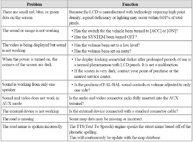
Troubleshooting
READ NEXT:
 Specifications, Components and Components Location | Description and Operation
Specifications
Specifications
Smart Key Unit
RF Receiver
Smart Key Fob
Antenna
Components and Components Location
Component Location (1)
Buzzer
Smart key unit
SEE MORE:
Battery saver function
This vehicle is equipped with a variety of
lights to illuminate the interior and exterior
of the vehicle.
CAUTION
To prevent the battery from being discharged,
do not leave the headlamp and
interior light on for a prolonged time
while the engine is not running.
Battery saver function
The pu
Adjustment - Repair procedures
Adjustment
Parking Brake Shoe Clearance Adjustment [2WD]
1. Raise the vehicle, and make sure it is securely supported.
2. Remove the rear tire and wheel.
3. Remove the plug from the disc.
4. Rotate the toothed wheel of adjuster by a screw driver until the disc is not
moving, and then retu
Content
- Home
- Kia Sportage - Fifth generation (NQ5) - (2022-2026) - Owner's Manual
- Kia Sportage - Second generation (JEKM) (2005-2015) - Body Workshop Manual
- Kia Sportage Third generation (SL) - (2011-2016) - Service and Repair Manual
- Sitemap
- Top articles
