Kia Sportage: Power Door Mirrors
Components and Components Location
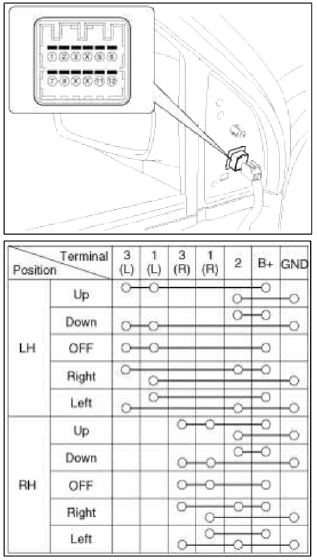
Component Location
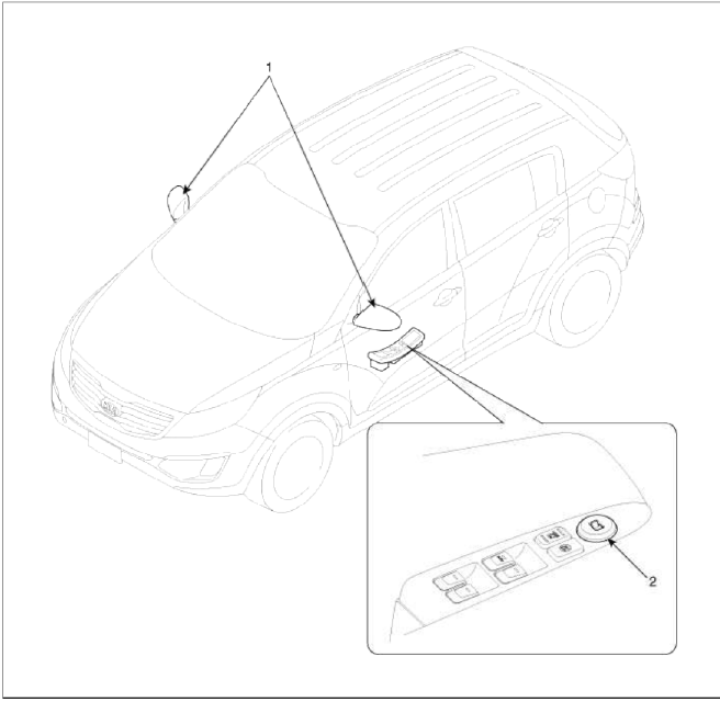
- Power door mirror
- Power door mirror switch
Power Door Mirror Switch
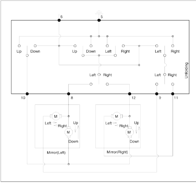
Schematic Diagrams
Circuit Diagram
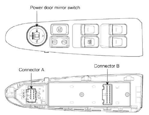
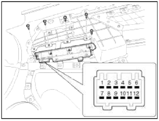
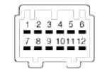 Connector A
- -
- -
- -
- Battery
- GND
- ACC
- -
- Driver door mirror motor (vertical)
- Driver door mirror motor (horizontal)
- Common
- Assist door mirror motor (horizontal)
- Assist door mirror motor (vertical)
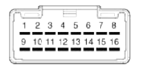 Connector Ð’
- Assist window switch up
- Assist window switch down
- Illumination
- -
- Door unlock
- Driver switch Auto
- Driver window switch up
- Driver window switch down
- Battery (+) R
- Rear right window switch up
- Rear right window switch down
- GND
- Door lock
- Rear left window switch up
- Rear left window switch down
- Battery (+) L
Repair procedures
Removal
Driver Door Mirror Switch
1. Disconnect the negative battery terminal.
2. Remove the front door trim.
(Refer to the BD group - "Front door")
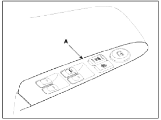
З. Remove the screws from power window switch (A) and connectors (B).
4. Remove the driver power window switch (A) from front door trim.
NOTE
Be careful not to damage the hook when removing the switch module.
Installation
Driver Door Mirror Switch
1. Install the driver power window switch and connectors.
2. Install the front door trim.
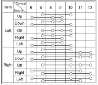
Inspection
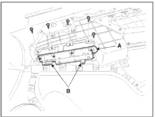
1. Remove the front door trim and power door mirror switch module (A).
2. Check for the continuity between terminals of power door mirror switch according to the table.
Power Door Mirror Actuator
Repair procedures
Inspection
1. Disconnect the negative (-) battery terminal.
2. Remove the front door delta cover.
(Refer to the BD group - "Front door")
3. Disconnect the connector from the door mirror.
4. Verify that the mirror operates properly as shown in the table.
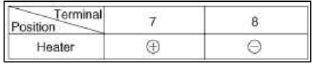
Mirror Heater
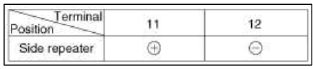
Turn Signal Lamp
READ NEXT:
 Components and Components Location | Description and Operation
Component Location
Driver power window main switch
Passenger window switch
Front window motor
Rear window motor
Rear window switch
Description and Operation
&nbs
SEE MORE:
Defogging inside windshield
When the windshield is covered with
frost or moisture, the front view is
blurred, you should remove the frost
and moisture.
WARNING
Windshield heating
Do not use the
or
position
during cooling operation in extremely
humid weather. The difference between
the temperature of the outside ai
Rear Body, Under Body
Rear Body
Body Repair
* These dimensions indicated in this figure are actual-measurement
dimensions.
Under Body
Body Repair
Projected Dimensions
* These dimensions indicated in this figure are actual-measurement
dimensions.
Actual-Measurement Dimensions
* These
Content
- Home
- Kia Sportage - Fifth generation (NQ5) - (2022-2026) - Owner's Manual
- Kia Sportage - Second generation (JEKM) (2005-2015) - Body Workshop Manual
- Kia Sportage Third generation (SL) - (2011-2016) - Service and Repair Manual
- Sitemap
- Top articles
