Kia Sportage: Blind-Spot Collision-Avoidance Assist (BCA)
Blind-Spot Collision-Avoidance Assist (BCA) (if equipped)
Blind-Spot Collision-Avoidance Assist is designed to help detect and monitor approaching vehicles in the driver's blind spot area and warn the driver of a possible collision with a warning message and audible warning.
In addition, if there is a risk of collision when changing lanes or driving forward out of a parking space, Blind-Spot Collision- Avoidance Assist will help avoid collision by applying the brake.
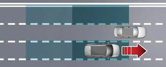
Blind-Spot Collision-Avoidance Assist helps detect and inform the driver that a vehicle is in the blind spot.
CAUTION
The detecting range may vary depending on the speed of your vehicle. However, even if there is a vehicle in the blind spot area, the function may not warn you when you pass by at high speeds.
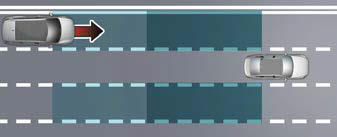
Blind-Spot Collision-Avoidance Assist helps detect and inform the driver that a vehicle is approaching at high speed from the blind spot area.
CAUTION
Warning Timing may vary depending on the speed of the vehicle approaching at high speed.
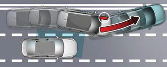 When changing lanes by detecting
the
lane ahead, if Blind-Spot Collision-Avoidance
Assist judges that there is a collision
risk with an approaching vehicle in
the blind spot, it will help avoid collision
by applying the brake.
When changing lanes by detecting
the
lane ahead, if Blind-Spot Collision-Avoidance
Assist judges that there is a collision
risk with an approaching vehicle in
the blind spot, it will help avoid collision
by applying the brake.
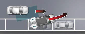 When you are driving forward out
of a
parking space, if Blind-Spot Collision-
Avoidance Assist judges that there is a
collision risk with an approaching vehicle
in the blind spot, it will help avoid collision
by applying the brake.
When you are driving forward out
of a
parking space, if Blind-Spot Collision-
Avoidance Assist judges that there is a
collision risk with an approaching vehicle
in the blind spot, it will help avoid collision
by applying the brake.
Detecting sensor
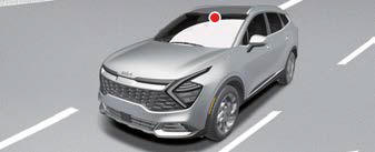
Front view camera
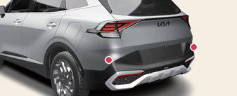
Rear corner radar
Refer to the picture above for the detailed location of the detecting sensors.
CAUTION
Take the following precautions to maintain optimal performance of the detecting sensor:
- Never disassemble the rear corner radar or radar assembly, or apply any impact on it.
- If there is impact on the rear corner radar or near the radar, even though the warning message does not appear on the cluster, Blind-Spot Safety system may not operate properly. Have the function inspected by an authorized Kia dealer.
- If the rear corner radars have been replaced or repaired, have the vehicle inspected by an authorized Kia dealer.
- Use only genuine parts to repair the rear bumper where the rear corner radar is located.
- Do not apply license plate frame or objects, such as a bumper sticker, film or a bumper guard near the rear corner radar.
- Blind-Spot Collision-Avoidance Assist may not work properly if the bumper has been replaced, or the surroundings of the rear corner radar has been damaged or paint has been applied.
- If a trailer, carrier or other equipments is installed, it may adversely affect the performance of the rear corner radar or the function may not operate.
For more details on the precautions of the front view camera, refer to "Forward Collision-Avoidance Assist (FCA) (Front Camera Only) (if equipped)"
- Blind-Spot Collision-Avoidance Assist settings
- Blind-Spot Collision-Avoidance Assist operation
- Blind-Spot Collision-Avoidance Assist malfunction and limitations
READ NEXT:
 Blind-Spot Collision-Avoidance Assist settings
Setting features
Blind-Spot Safety
Driver Assistance
Blind-Spot Safety
Active Assist
Warning Only
Off
With the engine on, select or deselect
Settings?Driver Assistance ? Blind
Blind-Spot Collision-Avoidance Assist operation
Blind-Spot Collision-Avoidance Assist
will warn and control as following operation.
Vehicle detection
Collision Warning
Collision-Avoidance Assist
Vehicle detection
Warning light will
Blind-Spot Collision-Avoidance Assist malfunction and
limitations
Check Blind-Spot Safety system
When Blind-Spot Collision-Avoidance
Assist is not working properly, the warning message will appear on the cluster
for several seconds, and the master
warni
SEE MORE:
Seat belt precautions
Take the following precautions when
using seat belts.
Infant or small child
All 50 states have child restraint laws.
You should be aware of the specific
requirements in your state. Child and/or
infant seats must be properly placed
and installed in the rear seat. For more
information about
Vehicle load limit
The vehicle load limit is displayed on
the tire and loading information
label on the driver's door.
Tire and loading information
label
The label located on the driver's
door sill gives the original tire size,
cold tire pressures recommended
for your vehicle, the number of people
tha
Content
- Home
- Kia Sportage - Fifth generation (NQ5) - (2022-2026) - Owner's Manual
- Kia Sportage - Second generation (JEKM) (2005-2015) - Body Workshop Manual
- Kia Sportage Third generation (SL) - (2011-2016) - Service and Repair Manual
- Sitemap
- Top articles
