Kia Sportage: Blower Unit | Blower Motor
Components and Components Location
Component Location
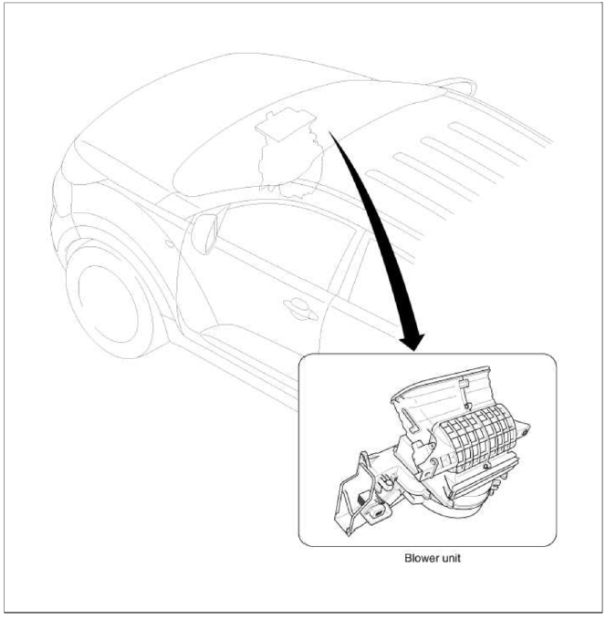
Components
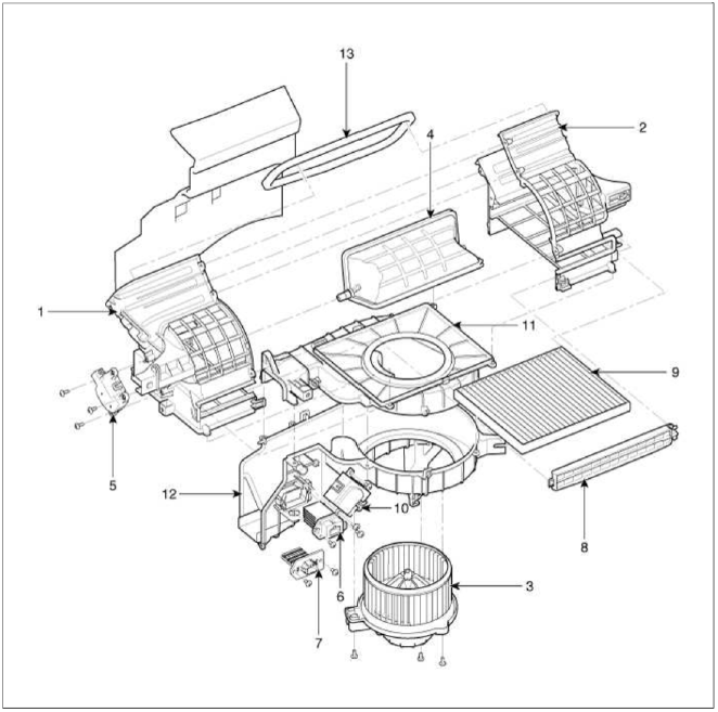
- Intake case (LH)
- Intake case (RH)
- Blower motor
- Intake door
- Intake actuator
- Mofet [Auto type]
- Resistor [Manual type]
- Climate control air filter cover
- Climate control air filter
- Ionizer
- Blower case (Upper)
- Blower case (Lower)
- Intake seal
Repair procedures
Replacement
1. Disconnect the negative (-) battery terminal.
2. Remove the crash pad and heater blower unit.
(Refer to HA group - "Heater Unit")
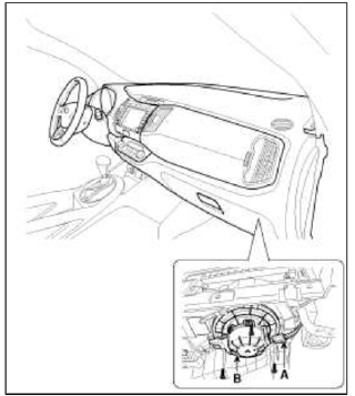
З. Remove the heater blower unit (A) from crash pad.
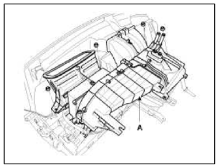
4. Remove the blower unit (A) from the heater unit (B) after loosening a mounting bolt and screws.
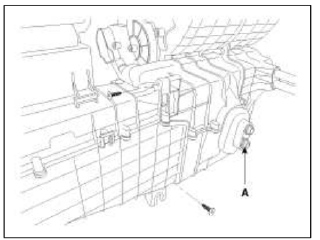
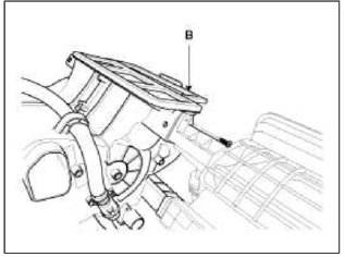
NOTE
Make sure that there is no air leaking out of the blower and duct joints.
5. Installation is the reverse order of removal.
Blower Motor
Repair procedures
Inspection
1. Connect the battery voltage and check the blower motor rotation.
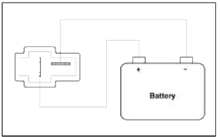
2. If the blower motor is not operating when voltage is applied, substitute with a known-good blower motor and check for proper operation.
3. If the problem is collected, replace the blower motor.
Replacement
1. Disconnect the negative (-) battery terminal.
2. Disconnect the connector (A) of the blower motor.
3. Remove the blower motor (B) after loosening the mounting screws.
4. Installation is the reverse order of removal.
READ NEXT:
 Power Mosfet | Blower Resistor | Climate Control Air Filter
Repair procedures
Inspection
1. Ignition "ON".
2. Manually operate the control switch and measure the voltage of blower motor.
З. Select the control switch to raise voltage unti
SEE MORE:
Description and Operation
Limitations Of The Navigation system
GPS Signal Reception State
As the GPS satellite frequency is received/transmitted in straight lines,
reception may not work if hiding devices are
placed on or near the GPS antenna or when traveling though the following
locations.
Tunnels
Luggage net holder
To keep items from shifting in the cargo
area, you can use the 4 holders located
in the cargo area to attach the luggage
net (if equipped), or you can fold the
luggage net into half and attach it
upwards by using the additional 2 holders
located on each side.
If necessary, contact an auth
Content
- Home
- Kia Sportage - Fifth generation (NQ5) - (2022-2026) - Owner's Manual
- Kia Sportage - Second generation (JEKM) (2005-2015) - Body Workshop Manual
- Kia Sportage Third generation (SL) - (2011-2016) - Service and Repair Manual
- Sitemap
- Top articles
