Kia Sportage: Components and Components Location | Instrument Cluster
Component Location
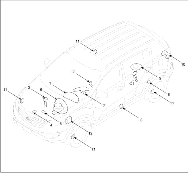
- Cluster assembly
- Seat belt switch
- Vehicle speed sensor
- Engine coolant temperature sender
- Oil pressure switch
- Brake fluid level warning switch
- Parking brake switch
- Door switch
- Fuel gauge sender
- Tailgate switch
- Wheel speed sensor
- ABS ECU
Instrument Cluster
Components and Components Location
Components
[General Type]
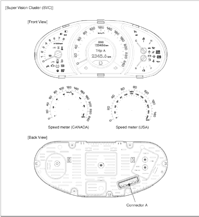
![[Super Vision Cluster (SVC) ]](images/books/1921/11/index%2063.png)
[Super Vision Cluster (SVC) ]
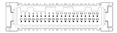 Connector Ð
- -
- Rheostat ground
- -
- -
- Rheostat output (illumination -)
- -
- Charge
- Water separator
- Oil pressure
- Airbag input -
- Airbag input +
- Check engine
- Immobilizer
- -
- Active ECO
- -
- ISG_DC
- -
- Ground signal
- Fuel ground (Fuel low)
- P ground
- AT P shift output
- AT R shift output
- AT N shift output
- AT D Shift output
- -
- 4 pin output
- Detent out
- Reset switch
- Mode switch
- Rheostat down
- Rheostat up
- Fuel input
- Ð’ CAN High
- Ð’ CAN Low
- C CAN High
- C CAN Low
- Illumination +
- IGN 1
- Battery +
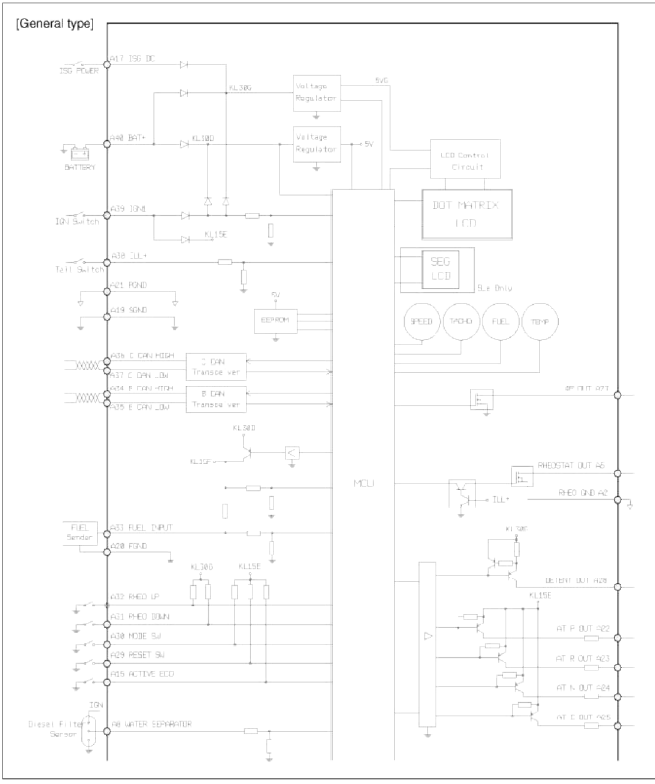
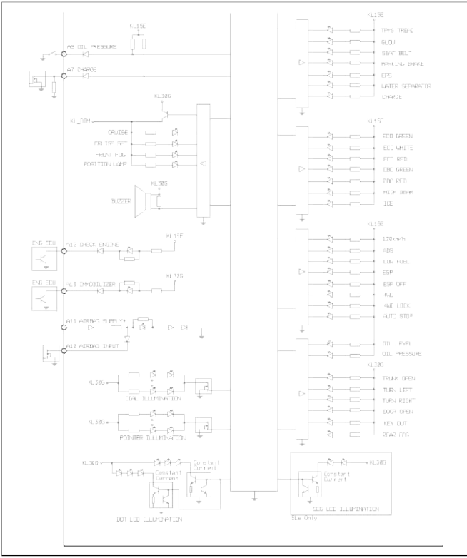
Schematic Diagrams
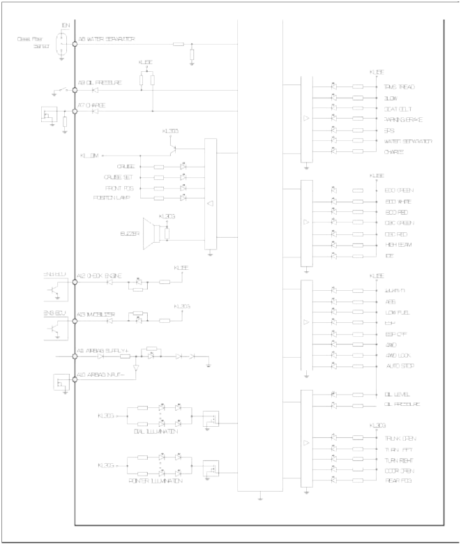
Circuit Diagram (1)
[General type]
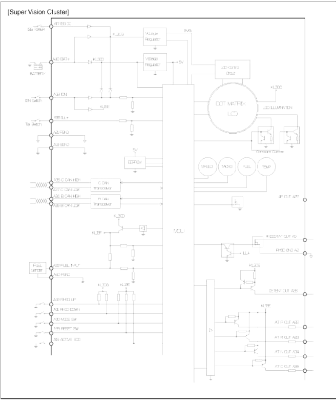
Circuit Diagram (2)
[Super Vision Cluster]
CLU1 message signal flow (Ð’ → C CAN gateway)
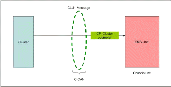
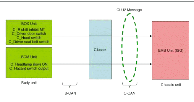
CLU2 message signal flow (Ð’ → C CAN gateway)
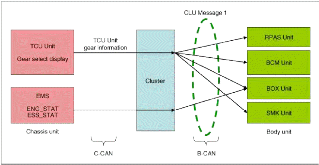
CLU message 1 signal flow (C → Ð’ CAN gateway)
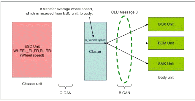
CLU message 3 signal flow (C → Ð’ CAN gateway)
Description and Operation
Description
ECO driving system
This system is designed to encourage eco-driving by providing real-time feedback to the driver.
The ECO indicator light assists you to drive in the most economical way.
The green indicator comes on when you drive with high fuel efficiency.
The fuel efficiency depends on driver's driving habit and road condition.
The system stops operation when the transaxle is in the P,R,N position or sports mode, or instantaneous fuel consumption mode is selected.
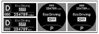
ECO indicator ON/OFF
1. ECO indicator system stops operation when instantaneous fuel consumption mode is selected.
2. ECO indicator light is always OFF when driver select the "ECO OFF" mode pushing the "Trip" button.
- Set the main LCD display to "ECO ON" pushing "Trip" button as below picture.
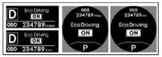
- And then set the "ECO OFF" pushing "Reset" button more than 1 second as below picture.
In this option. ECO indicator light does not operate any trip mode.
Repair procedures
Removal
1. Disconnect the negative (-) battery terminal.
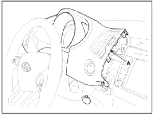
2. Remove the cluster fascia panel (A).
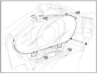
3. Remove the cluster assembly (A) after loosening 4 screws.
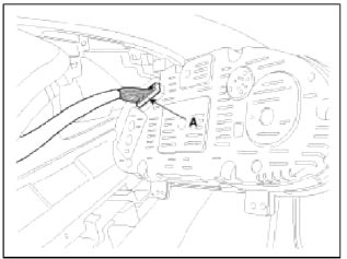
4. Disconnect the cluster fascia connector (A) and then remove the cluster.
Installation
1. Connect the cluster connector.
2. Install the cluster assembly.
3. Install the cluster fascia panel
Inspection
Speedometer
1. Adjust the pressure of the tires to the specified level.
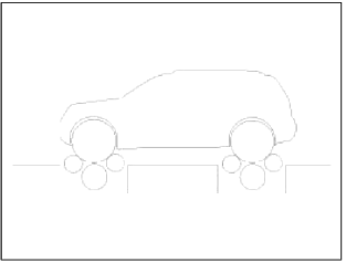
2. Drive the vehicle onto a speedometer tester. Use wheel chocks (A) as appropriate.
[2WD]
![[4WD]](images/books/1921/11/index%2079.png)
[4WD]
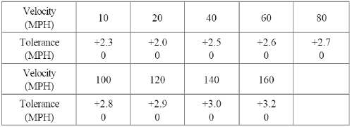
3. Check if the speedometer indicator range is within the standard values.
CAUTION
Do not operate the clutch suddenly or increase/ decrease speed rapidly while testing.
NOTE
Tire wear and tire over or under inflation will increase the indication error.
[Km/h]
![[MPH]](images/books/1921/11/index%2081.png)
[MPH]
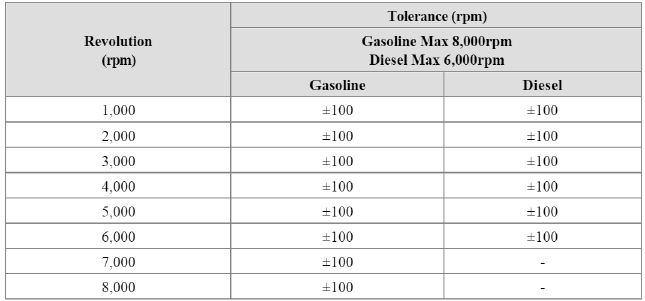
Tachometer
1. Connect the scan tool to the diagnostic link connector or install a tachometer.
2. With the engine stalled, compare the readings of the tester with that of the tachometer. Replace the tachometer if the tolerance is exceeded.
CAUTION
- Reversing the connections of the tachometer will damage the transistor and diodes inside.
- When removing or installing the tachometer, be careful not to drop it or subject it to severe shock.
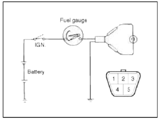
Fuel Gauge
1. Disconnect the fuel sender connector from the fuel sender.
2. Connect a 3.4 wattages, 12V test bulb to terminals 1 and 3 on the wire harness side connector.
3. Turn the ignition switch to the ON, and then check that the bulb lights up and the fuel gauge needle moves to full.
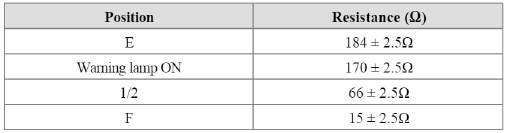
Fuel Gauge Sender
1. Using an ohmmeter, measure the resistance between terminals 1 and 3 of sender connector (A) at each float level.
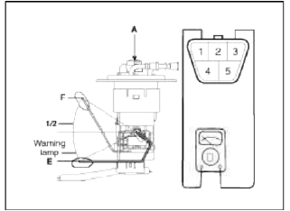
2. Also check that the resistance changes smoothly when the float is moved from "E" to "F".
3. If the height resistance is unsatisfied, replace the fuel sender as an assembly.
CAUTION
After completing this test, wipe the sender dry and reinstall it in the fuel tank.
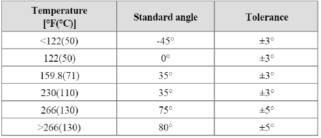
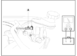
Engine Coolant Temperature Sender
1. Using an ohmmeter, measure the resistance between the terminal 2 and ground.
2. If the resistance value is not as shown in the table, replace the temperature sender.
Brake Fluid Level Warning Switch
1. Remove the connector (A) from the switch located at the brake fluid reservoir.
2. Verify that continuity exists between switch terminals 1 and 2 while pressing the switch (float) down with a rod.
Brake Fluid Level Warning Lamp
1. Ignition "ON".
2. Release the parking brake.
3. Remove the connector from the brake fluid level warning switch.
4. Ground the connector at the harness side.
5. Verify that the warning lamp lights.
Parking Brake Switch
The parking brake switch is a pull type. It is located at the side of the parking brake lever.
1. Check that there is continuity between the terminal and switch body with the switch (A) ON.
2. Check that there is no continuity between the terminal and switch body with the switch OFF.
If continuity is not as specified, replace the switch or inspect its ground connection.
[Pedal Type]
![[Lever Type]](images/books/1921/11/index%2089.png)
[Lever Type]
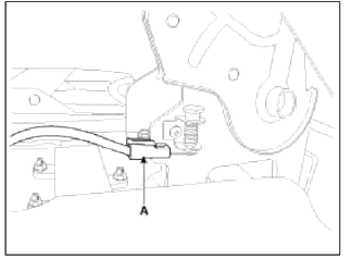
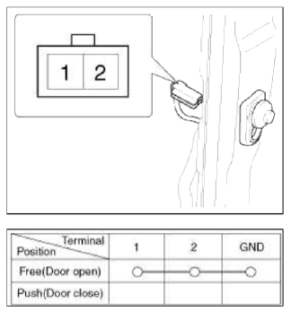
Door Switch
Remove the door switch and check for continuity between the terminals.
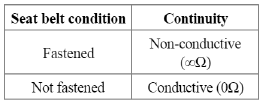
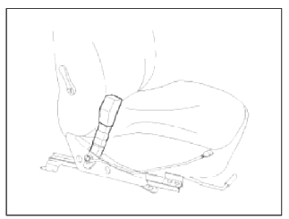
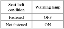
Seat Belt Switch
1. Remove the connector from the switch.
2. Check for continuity between terminals.
Seat Belt Warning Lamp
With the ignition switch turned ON, verify that the lamp glows.
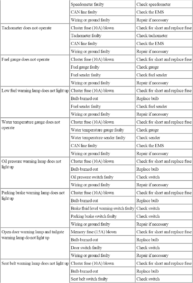
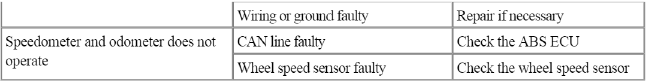
Troubleshooting
Troubleshooting

READ NEXT:
 Components and Components Location | Power Door Lock Actuators
Component Location
Driver power window switch
Assist power window switch
SJB (Smart Junction Box)
Door lock switch
Tailgate lock actuator & switch
Front doo
SEE MORE:
Back View Camera System
Components and Components Location
Component Location
Back view camera
ECM mirror
Schematic Diagrams
Circuit Diagram
Back view camera connector
Power
Video (+)
Ground
Video (-)
Description and Operation
Description
Back view camera will activate wh
Rear Disc Brake
Components and Components Location
Components
Guide rod bolt
Bleed screw
Caliper bracket
Caliper body
Inner pad shim
Brake pad
Pad retainer
Repair procedures
Removal
1. Remove the rear wheel & tire.
Tightening torque:
88.3 ~ 107.9 N.m (9.0 ~ 11.0 kgf.m, 65.1 ~ 79.
Content
- Home
- Kia Sportage - Fifth generation (NQ5) - (2022-2026) - Owner's Manual
- Kia Sportage - Second generation (JEKM) (2005-2015) - Body Workshop Manual
- Kia Sportage Third generation (SL) - (2011-2016) - Service and Repair Manual
- Sitemap
- Top articles
