Kia Sportage: Components and Components Location | Power Door Lock Actuators
Component Location
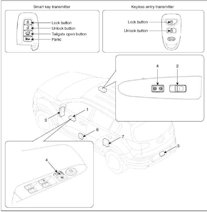
- Driver power window switch
- Assist power window switch
- SJB (Smart Junction Box)
- Door lock switch
- Tailgate lock actuator & switch
- Front door lock actuator & switch
- Rear door lock actuator & switch
Power Door Lock Actuators
Repair procedures
Inspection
Front Door Lock Actuator
1. Remove the front door trim.
(Refer to the BD group - "Front door")
2. Remove the front door module.
(Refer to the BD group - "Front door")
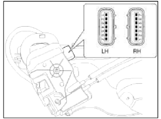
3. Disconnect the connectors from the actuator.
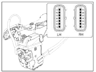
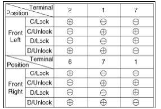
4. Check actuator operation by connecting power and ground according to the table. To prevent damage to the actuator, apply battery voltage only momentarily.
[Central Lock]
![[Double Lock]](images/books/1921/11/index%201.png)
[Double Lock]
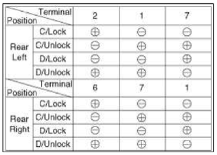
Rear Door Lock Actuator
1. Remove the rear door trim.
(Refer to the BD group - "Rear door")
2. Remove the rear door module.
(Refer to the BD group - "Rear door")
3. Disconnect the connectors from the actuator.
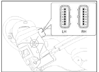
4. Check actuator operation by connecting power and ground according to the table. To prevent damage to the actuator, apply battery voltage only momentarily.
[Central Lock]
![[Double Lock]](images/books/1921/11/index%204.png)
[Double Lock]
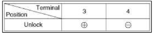
Tailgate Lock Actuator Inspection
1. Remove the tailgate trim.
(Refer to the BD group - "Tailgate")
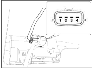
2. Disconnect the 4P connector from the actuator.
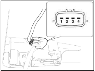
3. Check actuator operation by connecting power and ground according to the table. To prevent damage to the actuator, apply battery voltage only momentarily.
Front Door Lock Switch
1. Remove the front door trim.
(Refer to the BD group - "Front door")
2. Remove the front door module.
(Refer to the BD group - "Front door")
3. Disconnect the connectors from the actuator
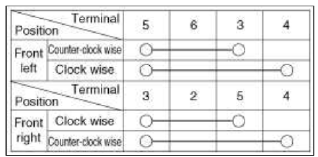
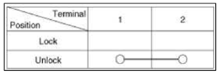
4. Check for continuity between the terminals in each switch position when inserting the key into the door according to the table.
[Central Lock]
![[Double Lock]](images/books/1921/11/index%209.png)
[Double Lock]
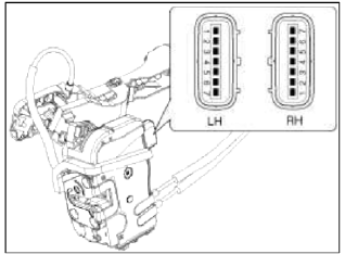
Rear Door Lock Switch
1. Remove the rear door trim.
(Refer to the BD group - "Rear door")
2. Remove the rear door module.
(Refer to the BD group - "Rear door")
3. Disconnect the connectors from the actuator.
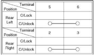
4. Check for continuity between the terminals in each switch position according to the table.
[Central Lock]
Tailgate Switch
1. Remove the tailgate trim.
(Refer to the BD group - "Tailgate")
2. Disconnect the 4P connector from the actuator.
3. Check for continuity between the terminals in each switch position according to the table.
READ NEXT:
 Power Door Lock Switch
Repair procedures
Inspection
Driver Power Door Lock Switch
1. Disconnect the negative battery terminal.
2. Remove the front door trim.
(Refer to the BD group - "Front door")
Power Door Mirrors
Components and Components Location
Component Location
Power door mirror
Power door mirror
switch
Power Door Mirror Switch
Schematic Diagrams
Circuit Diagram
Connecto
SEE MORE:
Operating rear window wiper and washer switch
The rear window wiper and washer
switch is located at the end of the wiper
and washer switch lever.
Turn the switch to the desired position
to operate the rear wiper and washer.
HI - Normal wiper operation
LO - Intermittent wiper operation
OFF - Wiper is not in operation
Pus
Hazardous driving conditions
If driving conditions deteriorate due to
poor weather or road conditions, you
should pay even more attention than
usual to your driving.
Hazardous driving conditions
When hazardous driving conditions are
encountered such as water, snow, ice,
mud, sand, or similar hazards, follow
these sugges
Content
- Home
- Kia Sportage - Fifth generation (NQ5) - (2022-2026) - Owner's Manual
- Kia Sportage - Second generation (JEKM) (2005-2015) - Body Workshop Manual
- Kia Sportage Third generation (SL) - (2011-2016) - Service and Repair Manual
- Sitemap
- Top articles
