Kia Sportage: Components and Components Location | Power Seat Motor | Power Seat Control Switch | Seat Heater Switch
Component Location
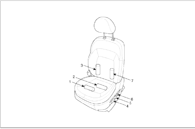
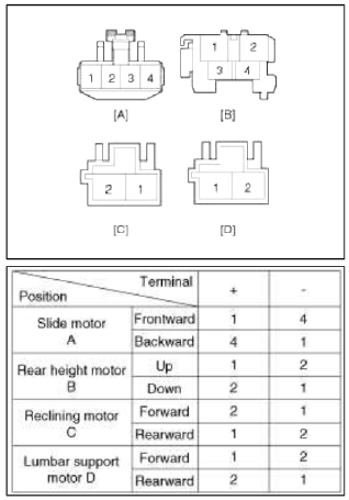
-
Slide motor
-
Rear height motor
-
Reclining motor
-
Power seat switch
-
Reclining switch
-
Lumbar support motor
Power Seat Motor
Repair procedures
Inspection
Power Seat Motor
1. Remove the front seat.
(Refer to BD group - "Front seat")
2. Disconnect the connectors for each motor.
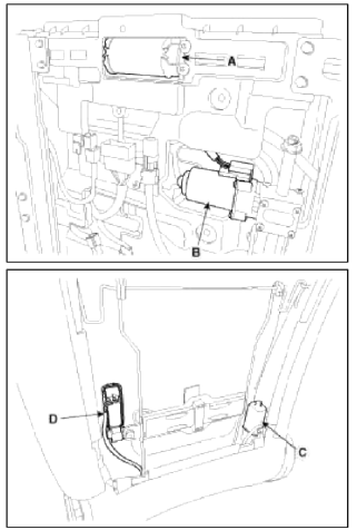
3. With the battery connected directly to the motor terminals, check if the motors run smoothly.
4. Reverse the connections and check that the motor turns in reverse.
5. If there is an abnormality, replace the motors.
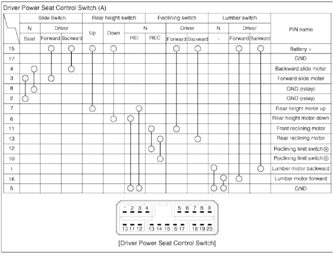
Power Seat Control Switch
Repair procedures
Inspection
1. With the power seat switch in each position, make sure that continuity exists between the terminals below. If continuity is not as specified, replace the power seat switch.
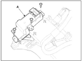
Removal
1. Disconnect the negative (-) battery terminal.
2. Remove the power seat recliner cover.
(Refer to the BD group - "Front seat")
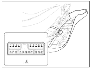
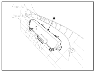
�—. Remove the power seat control switch (A).
Installation
1. Install the power seat control switch after connecting the connector.
2. Install the recliner cover and front power seat.
Seat Heater Switch
Repair procedures
Inspection
Driver / Assist seat
1. Disconnect the negative (-) battery terminal.
2. Remove the gear knob. Remove the floor console upper cover (A) using the appropriate tool.
(Refer to BD group - "Console")
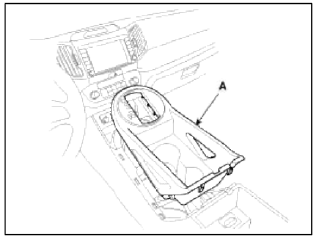
3. Remove the floor console tray (A).
NOTE
Take care not to damage the hook when removing the switch.
4. Disconnect the driver / assist seat heater switch connector.
![Driver [Heater]](images/books/1921/10/index%2094.png)
Driver [Heater]
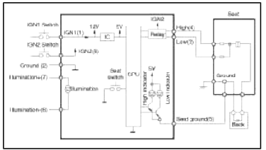
- IGN 1
- Ground
- Driver seat heater (Low)
- Driver seat heater (High)
- Indicator
- Illumination (+)
- Illumination (-)
- IGN 2
- -
- -
Driver [Ventilation + Heater]
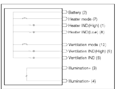
- Heater IND (High)
- Battery
- Illumination (+)
- Illumination (-)
- Ventilation IND (High)
- Ventilation IND (Low)
- Heater mode
- Heater IND (Low)
- -
- -
- -
- Ventilation mode
Assist [Heater]
- IGN 1
- Ground
- Assist seat heater (Low)
- Assist seat heater (High)
- Indicator
- Illumination (+)
- Illumination (-)
- IGN 2
- -
- -
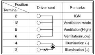
5. Operate each seat heater switch and check that continuity exists between the terminals.
[Heater]
![Driver [Ventilation + Heater]](images/books/1921/10/index%2098.png)
Driver [Ventilation + Heater]
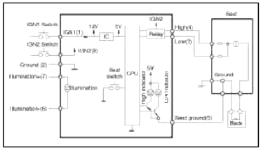
![Driver [Ventilation + Heater]](images/books/1921/10/index%2099.png)
Driver [Ventilation + Heater]
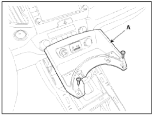
6. Inspect the switch pin. If needed, replace the seat heater switch (A) after loosening the screws (3EA).
Rear Seat Heater Switch
1. Disconnect the negative (-) battery terminal.
2. Remove the power window switch from the rear door trim.
(Refer to BE group - "Power window switch")
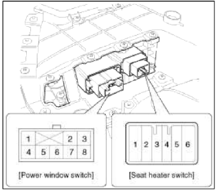
- Indicator (+)
- Indicator (-)
- IGN2
- Heater (+)
- Illumination (-)
- Illumination (+)
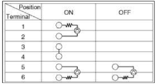
3. Inspect the switch pin. If needed, replace the seat heater switch.
READ NEXT:
SEE MORE:
 Preparation for assembly - Replacing body panel
Preparation for assembly
1. Spot weld finish
Use a disk grinder or similar tool to finish spot weld
mark. Do not grind more than is necessary to smooth
surface.
2. Panel preparation
Repair any bent or uneven areas with a hammer to
improve the assembly process.
3. Cutting a rough area for
Description and Operation, Components and Components Location | Oil Pump | Fluid
Description and Operation
Description
The hydraulic system consists of oil, an oil filter, an oil pump, and a valve body (valves and solenoid valves). The oil pump is powered by the engine. ATF passes through the oil filter and gets distributed along the oil channels. The oil becomes highl
Content
- Home
- Kia Sportage - Fifth generation (NQ5) - (2022-2025) - Owner's Manual
- Kia Sportage - Second generation (JEKM) (2005-2015) - Body Workshop Manual
- Kia Sportage Third generation (SL) - (2011-2016) - Service and Repair Manual
- Sitemap
- Top articles
