Kia Sportage: Description and Operation, Components and Components Location | Oil Pump | Fluid
Description and Operation
Description
The hydraulic system consists of oil, an oil filter, an oil pump, and a valve body (valves and solenoid valves). The oil pump is powered by the engine. ATF passes through the oil filter and gets distributed along the oil channels. The oil becomes highly pressurized as it exits the oil pump and passes through the line pressure valve before being fed to the clutch & brake control valve, clutch, and brakes. TCM controls the hydraulic pressure using solenoid valves and controls clutch and brake operations.
Components and Components Location
Components Location
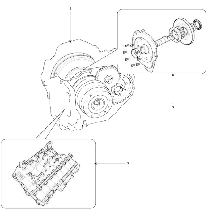
- Automatic transaxle
- Valve body assembly
- Oil pump assembly
Oil Pump
Description and Operation
Description
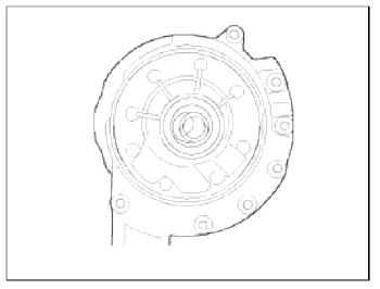
The oil pump is built-in as a single unit with the 26 brake chamber. Rotation of the pump builds the hydraulic pressure needed for the lubrication of the various parts of the transaxle and operation of the clutch and brakes. The oil also circulates through the torque converter and the cooler.
Components and Components Location
Components
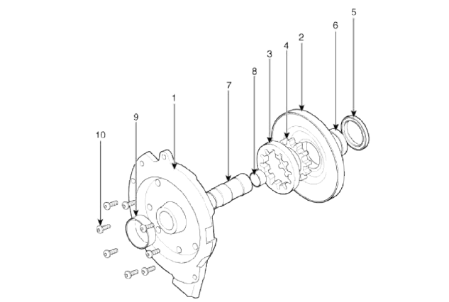
- Reaction shaft support assembly
- Oil pump housing
- Driven gear
- Drive gear
- Oil seal
- Bush-Housing
- Reaction shaft
- Bush-Reaction shaft
- Sleeve
- Bolt
Oil Pump Operation Flow
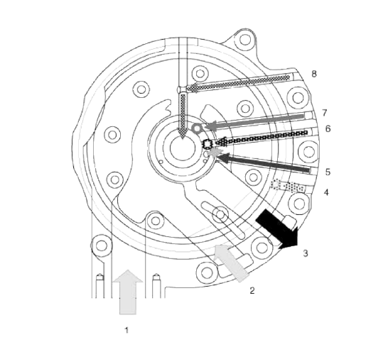
- Inhale (Oil filter)
- Inhale (Valve body)
- Outlet
- 26/B operation pressure
- 35R/C operation pressure
- Lubrication
- Line up clutch operation pressure
- Line up clutch cancellation
Fluid
Components and Components Location
Components Location
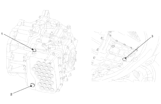
- Injection hole (eyebolt)
- Oil level ping
- Oil drain plug
Repair procedures
Service Adjustment Procedure
Oil level Check
NOTE
A check of ATF level is not normally required during scheduled services. If an oil leak is found, perform the oil level check procedure after repairs are completed.
CAUTION
When checking the oil level, be careful not to enter dust, foreign matters, etc. from fill hole.
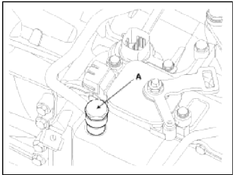
1. Remove the eyebolt (A).
Eyebolt tightening torque: 34.3 ~ 44.1 N.m (3.5 ~ 4.5 kgf.m 25.3 ~ 32.6 lb-ft)
CAUTION
Always replace the gasket of the eyebolt use new one whenever loosening eyebolt.
2. Add ATF SP-IV 700cc to the ATF injection hole.
3. Start the engine. Don't step on brake and accelerator simultaneously.
4. Confirm that the temperature of the A/T oil temperature sensor is 50-60ºC(122~140ºF) with the GDS.
5. Shift the select lever slowly from "P" to "D", then "D" to "P" and repeat one more at idle.
CAUTION
Keep on each speed position more than 2 sec.
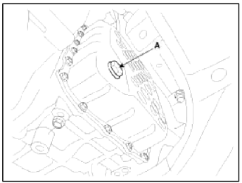
6. Lift the vehicle, then remove the oil level plug (A) from the valve body cover.
CAUTION
At this time, the vehicle must be at a level state.
7. If the oil flows out of the overflow plug in thin steady stream, the oil level is correct.
Then finish the procedure and tighten the oil plug.
NOTE
Oil level check (excess or shortage) method
- Excess: Oil flows out in thick stream.
- Shortage: No oil flows out of the overflow plug.
CAUTION
If there is no damage at the automatic transaxle and the oil cooler, the oil cooler hose, transaxle case, valve body tightening state are normal. ATF must drip out after performing above 1 to 7 procedures. After performing above 1 to 7 procedures, if the oil doesn't drip out, inspect the automatic transaxle assembly.
CAUTION
Replace the gasket of the oil level plug and use new one whenever loosening the oil level plug.
Oil level plug tightening torque: 34.3 ~ 44.1 N.m (3.5 ~ 4.5 kgf.m, 25.3 ~ 32.6 lb-ft)
8. Put down the vehicle with the lift and then tighten the eyebolt.
Replacement
NOTE
ATF of 6 speed automatic transaxle doesn't need to be replaced. If the vehicle is used severely in business or personal use, replace ATF every 60.000 miles.
Severe usage is defined as
- Driving in rough road (Bumpy, Gravel, Snowy, Unpaved road, etc.)
- Driving in mountain road, ascent/descent
- Repetition of short distance driving
- More than 50% operation in heavy city traffic during hot weather above 32ºC (89.6ºF).
- Police, Taxi, Commercial type operation or trailer towing, etc.
1. Remove the drain plug (A) and reinstall the drain plug after draining ATF totally
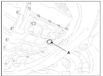
Drain plug tightening torque: 34.3 ~ 44.1 N.m (3.5 ~ 4.5 kgf.m, 25.3 ~ 32.6 lb-ft)
CAUTION
The gasket of the drain plug use new one.
2. Fill the oil about 5 liters through eyebolt.
3. Check the oil level. (Refer to "Hydraulic system (Fluid)" in this group)
READ NEXT:
 Valve Body
Description and Operation
Description
The valve body is essential to automatic transaxle control and consists of
various valves used to control the oil feed
from the oil pump. Specifically,
SEE MORE:
Smart Cruise Control conditions not satisfied
A: Smart Cruise Control conditions not
met
If the Driving Assist button, + switch, -
switch or ( 3) switch is operated when
Smart Cruise Control's operating conditions
are not satisfied, a warning message
will appear on the cluster, and an
audible warning will sound.
In traffic situa
Blind-Spot Collision-Avoidance Assist operation
Blind-Spot Collision-Avoidance Assist
will warn and control as following operation.
Vehicle detection
Collision Warning
Collision-Avoidance Assist
Vehicle detection
Warning light will appear in the outside
rear view mirror when the vehicle on
both lanes is detected from the rear.
Content
- Home
- Kia Sportage - Fifth generation (NQ5) - (2022-2026) - Owner's Manual
- Kia Sportage - Second generation (JEKM) (2005-2015) - Body Workshop Manual
- Kia Sportage Third generation (SL) - (2011-2016) - Service and Repair Manual
- Sitemap
- Top articles
