Kia Sportage: Components and Components Location | Repair procedures
Component
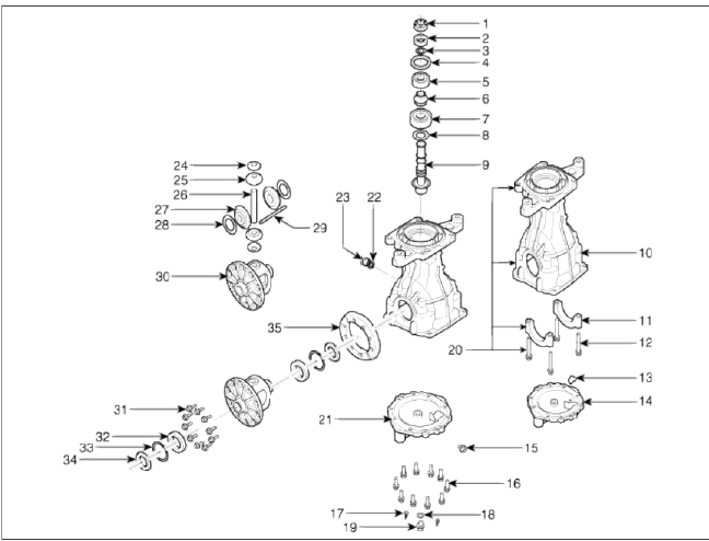
- Drive pinion nut
- Oil seal
- O-ring
- Oil seal
- Front bearing
- Spacer
- Rear bearing
- Inner shim
- Drive pinion gear
- Differential carrier
- Bearing cap
- Bearing cap bolt
- Plate baffle
- Carrier cover
- Vent plug
- Cover fix bolt
- Dower pin
- Filler gasket
- Filler plug
- Carrier sub assembly
- Cover sub assembly
- Drain plug gasket
- Drain plug
- Diff pinion washer
- Diff pinion
- Diff shaft
- Diff gear
- Diff gear washer
- Lock pin
- Diff case
- Ring gear bolt
- Diff bearing
- Diff shim
- Diff oil seal
- F/driven gear
Repair procedures
Replacement
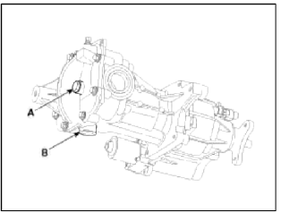
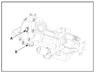
1. Drain the differential gear oil.
NOTE
Filler plug (A) & Drain plug (B) tightening torque.
Tightening torque
Filler plug (A): 39.2 ~ 58.8 N.m (4.0 ~ 6.0 kgf.m 28.9 ~ 43 lb-ft)
Drain plug (B): 49.0 ~ 68.6 N.m (5.0 ~ 7.0 kgf.m, 36.2 ~ 50.6 lb-ft)
2. Remove the rear drive shaft. (Refer to rear drive shaft.)
3. Remove the propeller shaft. (Refer to propeller shaft.)
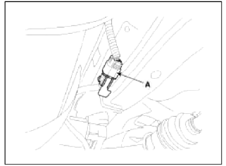
4. Disconnect the coupling control connector wire clip (A).
5. Disconnect the coupling control connector (A).
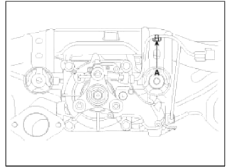
6. Support the differential assembly (A) with the jack.
Tightening torque: 68.6 ~ 88.3N.m (7.0 ~ 9.0kgfm , 50.6 ~ 65.1lb-ft)
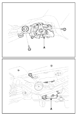
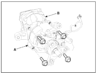
7. After loosen the bolt and then remove the differential carrier (B) from the coupling (A).
8. Install in the reverse order of removal.
9. Add diff gear oil fluid to differential carrier.
NOTE
Filler ping (A) & Drain ping (B) tightening torque.
Tightening torque
Filler plug (A): 39.2 ~ 58.8 N.m (4.0 ~ 6.0 kgf.m 28.9 ~ 43 lb-ft)
Drain plug (B): 49.0 ~ 68.6 N.m (5.0 ~ 7.0 kgf.m, 36.2 ~ 50.6 lb-ft)
Inspection
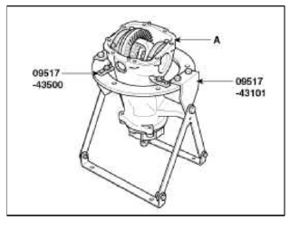
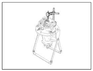
Install the differential carrier assembly (A) with the special tools (09517-43401 & 09517-43 500).Then carry out the following inspection.
1. Check the final drive gear backlash by the following procedure.
- Place the drive pinion and move the drive gear to check backlash is within the standard range.
NOTE
Measure at 4 points on the gear periphery.
Standard value: 0.10 ~ 0.15mm (0.0039 ~ 0.0059in.)
2. Check the drive gear back-face lash by the following procedure.
- Place a dial gauge on the back-face of the drive gear and measure the runout
Limit: 0.05 mm (0.002 in)
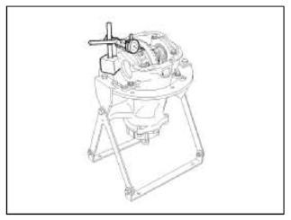
- If the runout is beyond the limit, check that there are no foreign substances between the drive gear and differential case and, that the bolts fixing the drive gear are not loose.
3. Check the differential gear backlash by the following procedure.
- Fix the side gear with a wedge so it cannot move and measure the differential gear backlash with a dial indicator on the pinion gear.
Standard value: 0 ~ 0.05 mm (0 ~ 0.002 in)
NOTE
Take the measurements at two places on the pinion gear.
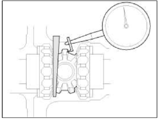
- If the backlash exceeds the limit, adjust using side bearing spacers.
NOTE
If adjustment is impossible, replace the side gear and pinion gear as a set.
4. Check the tooth contact of the final drive gear by the following procedure.
- Apply the same amount of machine blue slightly to both surfaces of the drive gear teeth.
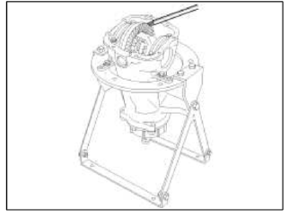
- Insert a brass rod between the differential carrier and the differential case, and then rotate the companion flange by hand (once in the normal direction, and then once in the reverse direction) while applying a load to the drive gear so that some torque (approximately 25~30Nm) is applied to the drive pinion.
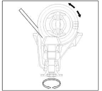
CAUTION
If the drive gear is rotated too much, the tooth contact pattern will become unclear and difficult to check.
- Check the tooth contact pattern.
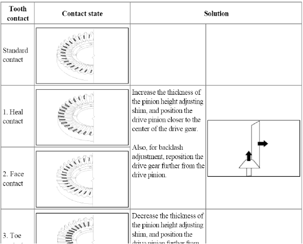
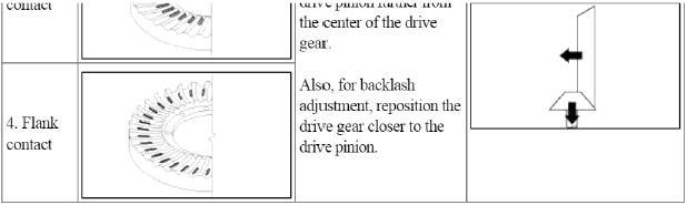
NOTE
- Tooth contact pattern is a method for judging the result of the adjustment of drive pinion height and final drive gear backlash. The adjustment of drive pinion height and final drive gear backlash should be repeated until the tooth contact patterns are similar to the standard tooth contact pattern.
- When you cannot obtain a correct pattern, the drive gear and drive pinion have exceeded then limits. Both gear s should be replaced as a set.
5. Check the oil leaks and the lip part for chew or wear.
6. Check the bearings for wear or discoloration.
7. Check the gear carrier for cracks.
8. Check the drive pinion and drive gear for wear or cracks.
9. Check the side gears, pinion gears and pinion shaft for wear or damage.
10. Check the side gear spline for wear or damage.
READ NEXT:
SEE MORE:
 In case of an emergency
If the electrical power door lock switch is
not operating (e.g., dead car battery) the
only way to lock the door(s) is with the
mechanical key from the outside key
hole.
Doors without an outside key hole can
be locked as follows:
Open the door.
Insert the key into the emergency
CVVT Oil Temperature Sensor (OTS)
Description and
Operation
Description
Continuous Variable Valve Timing (CVVT) system advances or retards the valve
tuning of the intake and exhaust
valve in accordance with the ECM control signal which is calculated by the
engine speed and load.
By controlling CWT , the valve over-l
Content
- Home
- Kia Sportage - Fifth generation (NQ5) - (2022-2026) - Owner's Manual
- Kia Sportage - Second generation (JEKM) (2005-2015) - Body Workshop Manual
- Kia Sportage Third generation (SL) - (2011-2016) - Service and Repair Manual
- Sitemap
- Top articles
