Kia Sportage: Components and ComponentsLocation | Removal - Repair procedures
Components (1)
[Hand Type] / [Foot Type]
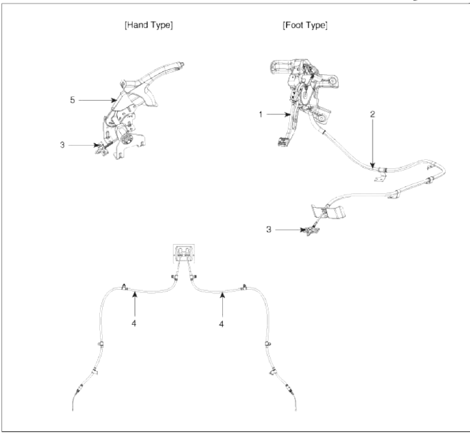
- Parking brake pedal assembly
- Front parking brake cable (Foot type only)
- Equalizer assembly
- Rear parking brake cable
- Parking brake lever assembly
Components (2)
[2WD]
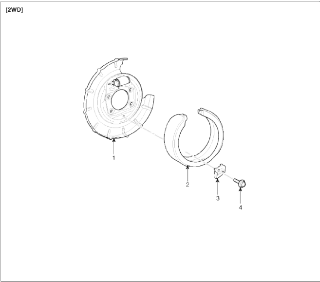
- Backing plate
- Brake shoe
- Shoe hold clip
- Bolt
Components (3)
[4WD]
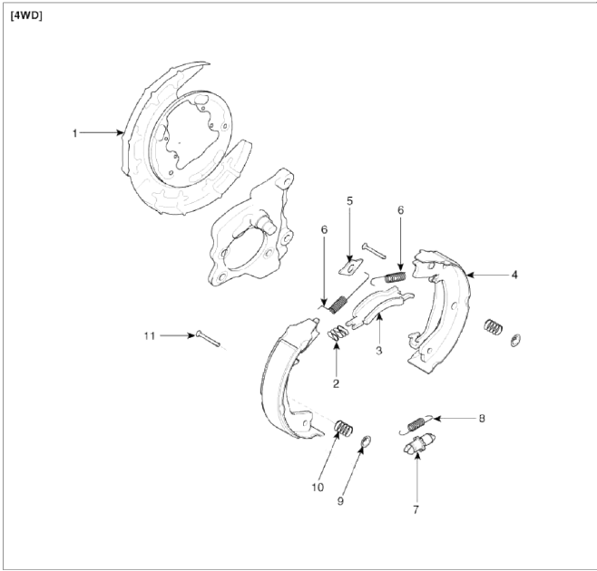
- Backing plate
- Strut spring
- Strut
- Shoe and lining
- Shoe guide
- Return spring
- Adjuster
- Return spring
- Cup washer
- Shoe hold down spring
- Shoe hold down pin
Removal - Repair procedures
Removal
Parking Brake Pedal [Foot type]
1. Remove the crash pad lower panel and reinforcement panel. (Refer to the Body group-crash pad)
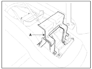
2. Remove the junction box. (Refer to the Body Electrical System group - Fuses and Relays
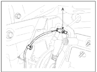
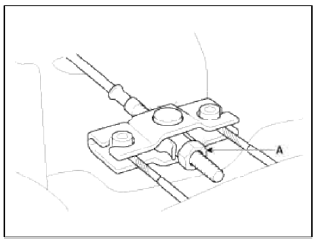
3. Disconnect the parking brake switch connector (A).
4. Remove the parking brake cable mounting nut (A).
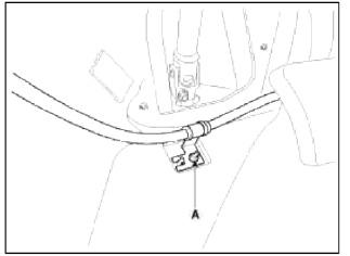
5. Remove the parking brake pedal mounting bolts (A) and nut (B).
6. Remove the parking brake cable adjusting nut (A) and the fixing clip (B) and then remove the parking brake pedal.
7. Remove the floor console. (Refer to the Body group - Console)
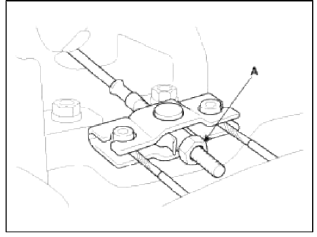
8. Remove the floor console bracket (A).
9. Remove the parking brake cable fixing clip (A) and bolts (B).
10. Loosen the adjusting nut (A) and then remove the front parking brake cable.
11. Raise the vehicle, and make sure it is securely supported.
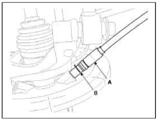
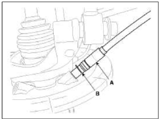
12. Remove the parking brake cable (A) after removing the retaining ring (B).
13. Loosen the parking brake cable bracket bolts and remove the rear parking brake cable.
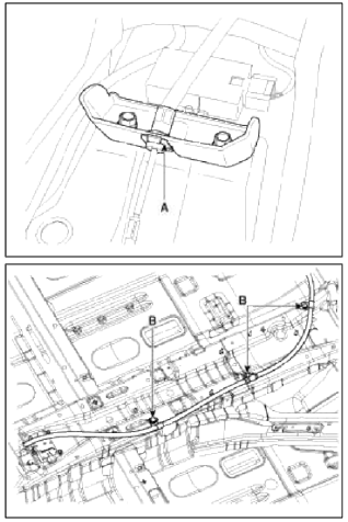
Parking Brake Lever [Hand type]
1. Remove the floor console. (Refer to the Body group - Console)
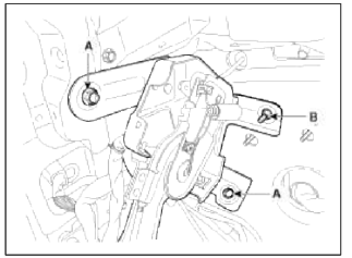
2. Disconnect the connector (A) of parking brake switch.
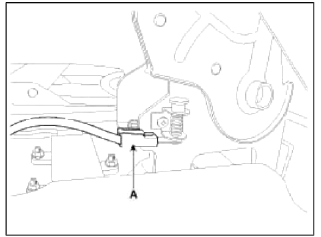
3. Remove the floor console bracket (A).
4. Loosen the adjusting nut (A) and remove the parking brake cables.
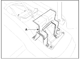
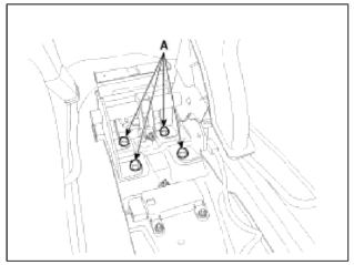
5. Remove the parking brake lever assembly after removing the 4 bolts (A) as shown below.
6. Raise the vehicle and make sure it is securely supported.
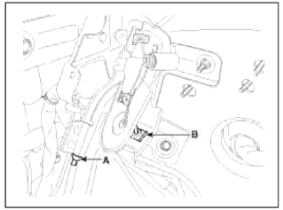
7. Remove the parking brake cable (A) after removing the retaining (B).
8. Loosen the parking brake cable bracket bolts and remove the parking brake cable.
Parking Brake Shoe [2WD]
1. Raise the vehicle, and make sure it is securely supported.
2. Remove the rear tire and wheel.
3. Remove the rear brake caliper and Rear disc brake.
(Refer to "Rear disc brake removal")
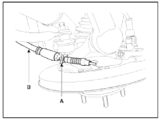
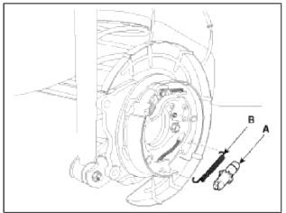
4. Remove the parking brake cable (B), after removing the clip (A).
5. Remove the hub assembly and parking brake assembly.
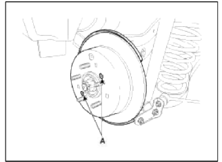
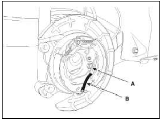
6. Loosen the shoe hold clip mounting bolt (A) and then remove the brake shoe.
![Parking Brake Shoe [4WD]](images/books/1921/14/index%2095.png)
Parking Brake Shoe [4WD]
1. Raise the vehicle, and make sure it is securely supported.
2. Remove the rear tire and wheel, then remove the brake caliper. (Refer to "Rear disc brake removal")
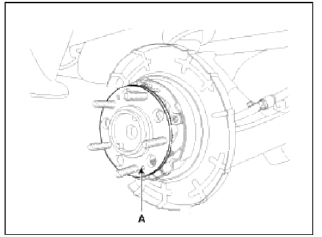
3. Remove the rear brake disc by loosening the screws (A).
4. Remove the rear hub unit bearing (A).
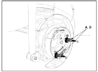
5. Remove the shoe hold down pin (A) and the spring (B) by pushing the retainer spring and turning the pin.
6. Remove the adjuster assembly (A) and the return spring (B).
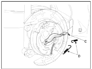
7. Remove the parking brake cable (B) from the brake shoe (A).
8. Remove the strut (C) and the shut spring (D).
9. Remove the brake shoe.
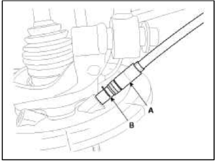
10. Remove the parking brake cable retaining (B), from the parking brake cable (A).
READ NEXT:
 Installation - Repair procedures
Installation
Parking Brake Shoe [2WD]
1. Install the brake shoe.
2. Fix the brake shoe with shoe hold clip and then install the bolt (A).
Tightening torque:
2.0 ~ 4.9 N.m (0.2 ~ 0.5 kgf.m, 1.4 ~
Adjustment - Repair procedures
Adjustment
Parking Brake Shoe Clearance Adjustment [2WD]
1. Raise the vehicle, and make sure it is securely supported.
2. Remove the rear tire and wheel.
3. Remove the plug from the disc.
4.
SEE MORE:
Welcome system
The welcome system is a function that
illuminates the surroundings or the interior
when the driver approaches or exits
the vehicle.
Door handle lamp (if equipped)
When all the doors (and liftgate) are
closed and locked, the door handle lamp
will come on for about 15 seconds if any
of the
Tire | Wheel
Repair procedures
Tire wear
1. Measure the tread depth of the tires.
Tread depth [limit]: 1.6 mm (0.063 in.)
2. If the remaining tread (A) depth is less than the limit, replace the tire.
NOTE
When the tread depth of the tires is less than 1.6 mm(0.063 in.), the wear indicators (B) will appear
Content
- Home
- Kia Sportage - Fifth generation (NQ5) - (2022-2026) - Owner's Manual
- Kia Sportage - Second generation (JEKM) (2005-2015) - Body Workshop Manual
- Kia Sportage Third generation (SL) - (2011-2016) - Service and Repair Manual
- Sitemap
- Top articles
