Kia Sportage: Description and Operation, Components and Components Location | Flow Diagram
Description and Operation
Description
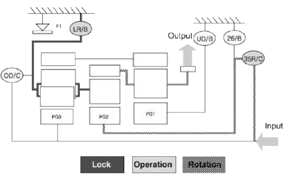
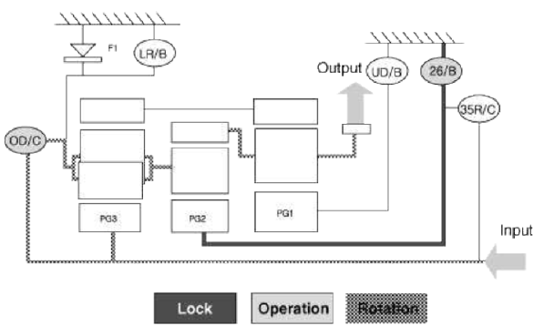
The 6-spd automatic transaxle consists of an overdrive clutch (OD/C), a one-way clutch (OWC), a lower and reverse brake (LR/B), an underdrive brake (UD/B), a 26 brake (26/B). and a 35R clutch (35R/C). These clutches and brakes are operated by controlling the hydraulic pressure.
Components and Components Location
Components Location
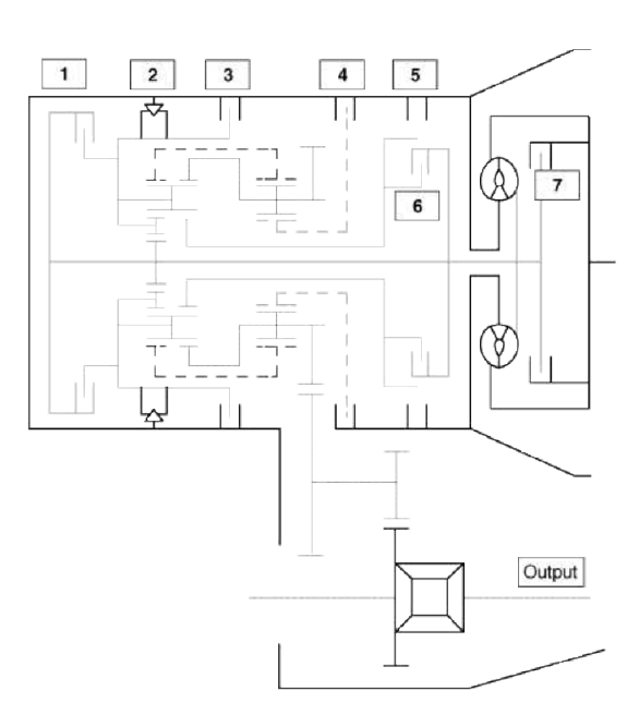
- Overdrive clutch (OD/C)
- One way clutch (OWC)
- Low & Reverse brake (LR/B)
- Underdrive brake (UD/B)
- 26 brake(26/B)
- 35R clutch (35R/C)
- Damper clutch (D/C)
Flow Diagram
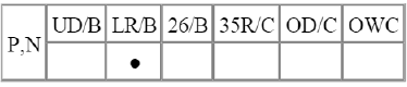
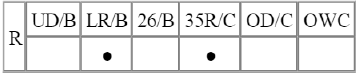
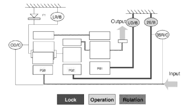
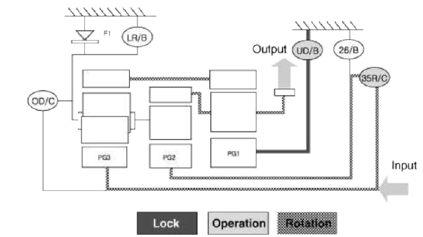
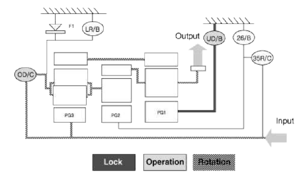
Power Flow Chart
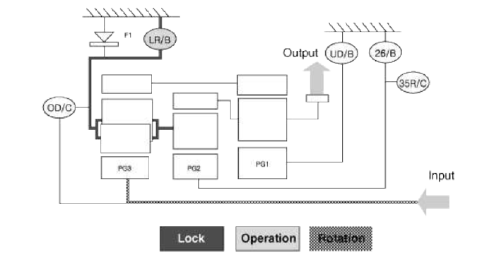
Direction of Rotation
Lower & Reverse Brake (LR/B) Activation → Overdrive (O/D) Hub Lock → Mid & Rear Р/С Lock Input Shaft Rotation → Rear Sun Gear Rotation → Rear Inner Pinion Rotation (Reverse) → Rear Outer Pinion
Rotation → Rear Annulus Gear Rotation → Front Annulus Gear Rotation → Front Pinion Rotation → Front Sun Gear Rotation (Reverse) → Underdrive (U/D) Hub Rotation (Reverse)
Input shaft rotation → Overdrive Clutch (OD/C) Retainer Rotation Input shaft rotation → 35R Clutch Rotation
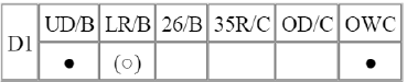
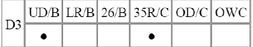
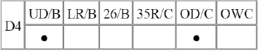
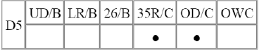
Power Delivery Route
Middle carrier locked and middle sun gear in rotation
Rotating the middle planetary gear's sun gear while its carrier is locked in place slows down and reverse rotates the annulus gear (front carrier), resulting in power transfer to the front carrier.
The rear planetary gear's rear and front annulus gears rotate at a reduced rate, resulting in reverse, zero load rotation of the front planetary gear's front sun gear.
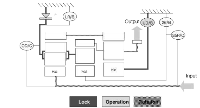
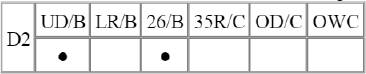
Power Delivery Route
Front sun gear and middle & rear carrier locked and rear sun gear in constant rotation
When the rear sun gear is rotated, power is reduced at the rear planetary gear and then delivered to the rear and front annulus gears. The power is then reduced again at the front planetary gear, whose sun gear is locked in place, and then delivered to the front carrier.
Here, the middle annulus gear, which comprises of a single unit with the front carrier, rotates and results in reverse, zero load rotation of the middle sun gear.
Power Delivery Route
Front sun gear and middle sun gear locked and rear sun gear in constant rotation
Rotating the rear sun gear delivers power to the rear & front annulus gears, and reaction from the front carrier and the middle annulus gear, to which the sun gear is attached, transfers to the middle and rear carriers, resulting in power equilibrium and power transfer to the front carrier.
Power Delivery Route
Front sun gear locked and middle and rear sun gears in rotation
Rotating the middle sun gear and the rear sun gear transfers power to the rear and front annulus gears, and reaction from the front carrier and the middle annulus gear, to which the sun gear is attached, transfers to the middle and rear carriers, resulting in power equilibrium and power transfer to the front carrier.
Power Delivery Route
Front sun gear locked and rear carrier and rear sun gears in rotation
Activation of the overdrive clutch (OD/C) synchronizes the rear planetary gear's carrier and sun gears. The 1:1 rotation ratio passes through the rear and front annulus gears and reaches the front planetary gear's front carrier, to which the sun gear is attached.
Here, the middle planetary gear's middle sun gear rotates at a faster rate in the normal direction and at zero load due to the actions of the reduced annulus gear and the carrier having a 1:1 rotation ratio.
Power Delivery Route
Middle and rear carriers, middle sun gear, and rear sun gear in rotation
The middle planetary gear's middle carrier and sun gear rotate simultaneously, resulting in the 1:1 rotation ratio being transferred to the middle annulus gear (front carrier).
Here, the rear planetary gear rotates in a 1:1 rotation ratio, as it would when the 4th gear is engaged: however, the front planetary gear remains unrestrained and the front sun gear rotates in the normal direction, at a zero load, and at a rotation ratio of 1:1.
Power Delivery Route
Middle carrier in rotation and middle sun gear locked
When the middle planetary gear's sun gear is locked in place and the train's carrier's allowed to rotate, the middle annulus gear increases its rate of rotation and transfers power to the front carrier.
Here, the rear planetary gear maintains a 1:1 rotation ratio as it would when 4th or 5th gear is engaged; however, the front planetary gear remains unrestrained and the front sun gear rotates at a faster rate in the normal direction and at zero load.
READ NEXT:
 Description and Operation
Description
Automatic transaxle system relies on various measurement data to determine
the current control status and
extrapolate the necessary compensation values. These values are used to
SEE MORE:
Conditions and operation of the front passenger ODS
*1. The system judges a person of adult size as an adult. When a smaller
adult sits in the front passenger
seat, the system may recognize him/her as a child depending on his/her physique
and posture.
*2. Do not allow children to ride in the front passenger seat. When a larger
child who h
Good braking practices
Good braking practices help keep occupants
safe and extend brake life.
Check to be sure the parking brake is
not engaged and the parking brake
indicator light is out before driving
away.
Driving through water may get the
brakes wet. They can also get wet
when the vehicle is washed.
Content
- Home
- Kia Sportage - Fifth generation (NQ5) - (2022-2026) - Owner's Manual
- Kia Sportage - Second generation (JEKM) (2005-2015) - Body Workshop Manual
- Kia Sportage Third generation (SL) - (2011-2016) - Service and Repair Manual
- Sitemap
- Top articles
