Kia Sportage: Description and Operation, Specifications, Troubleshooting, Schematic Diagrams | Components and Components Location
Kia Sportage Third generation (SL) - (2011-2016) - Service and Repair Manual / Emission Control System / General Information / Description and Operation, Specifications, Troubleshooting, Schematic Diagrams | Components and Components Location
Description and Operation
Description
Emissions Control System consists of thee major systems.
- The Crankcase Emission Control System prevents blow-by gas from releasing into the atmosphere. This system recycles gas back into the intake manifold (Closed Crankcase Ventilation Type).
- The Evaporative Emission Control System prevents evaporative gas from releasing into the atmosphere. This system bums gas at appropriate engine operating condition after gathering it in the canister.
- The Exhaust Emission Control System converts the thee pollutants [hydrocarbons (HC), carbon monoxide (CO), and oxides of nitrogen (NOx)] into harmless substances by using the 3-way catalytic converter.
Specifications
Specifications
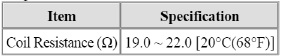
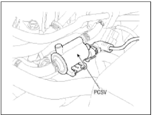
Purge Control Solenoid Valve (PCSV)
Specification
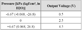
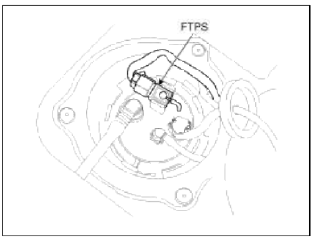
Fuel Tank Pressure Sensor (FTPS)
Type: Piezo-Resistive Pressure Sensor
Specification
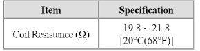
Canister Close Valve (CCV)
Specification
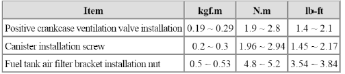
Tightening Torques
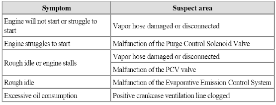
Troubleshooting
Troubleshooting
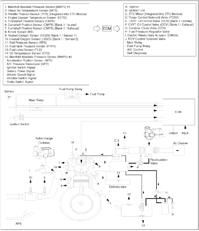
Schematic Diagrams
Schematic Diagram
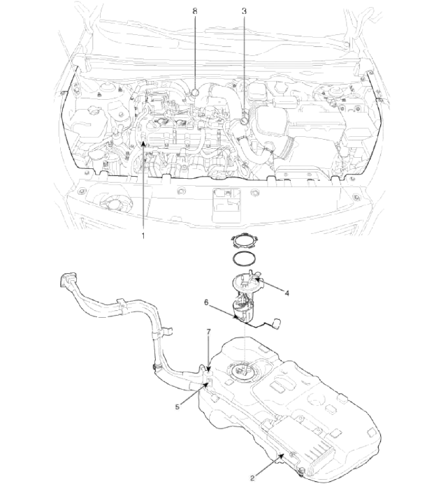
Components and Components Location
Components Location
- PCV valve
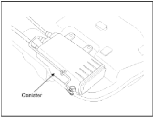
- Canister
- Purge control solenoid valve (PCSV)
- Fuel tank pressure sensor (FTPS)
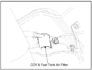
- Canister close valve (CCV)
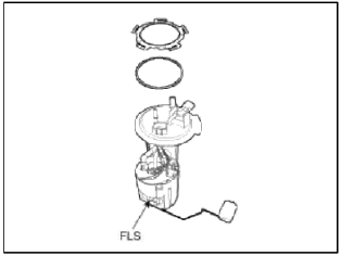
- Fuel level sensor (FLS)
- Fuel tank air filter
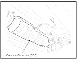
- Catalytic converter (CCC)
1. PCV Valve
2. Canister
3. Purge Control Solenoid Valve (PCSV)
4. Fuel Tank Pressure Sensor (FTPS)
5. Canister Close Valve (CCV)
7. Fuel Tank Air Filter
6. Fuel Level Sensor (FLS)
8. Catalytic converter (CCC)
READ NEXT:
 Schematic Diagrams, Repair procedures | Positive Crankcase Ventilation (PCV) Valve
Schematic Diagrams
Schematic Diagram
Repair procedures
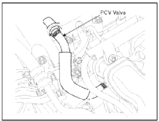
Inspection
1. After disconnecting the vapor hose from the PCV valve, remove the PCV valve.
2. Reconnect the PCV valve to the vapor
SEE MORE:
Vehicle settings (infotainment system) (if equipped)
Press the Settings button on the head
unit of the infotainment system.
Select Vehicle and change the setting
of the features.
Vehicle Settings in the infotainment system
provides user options for a variety
of settings including door lock/unlock
features, convenience features, driv
Front Seat
Components and Components
Location
Components
Headrest
Headrest guide
Front seat back cover
Front seat back heater
Front seat back pad
Front seat back power lumbar
Front seat back duct
Front seat back frame
Front seat back cover
Front seat map pocket
Front inside co
Content
- Home
- Kia Sportage - Fifth generation (NQ5) - (2022-2026) - Owner's Manual
- Kia Sportage - Second generation (JEKM) (2005-2015) - Body Workshop Manual
- Kia Sportage Third generation (SL) - (2011-2016) - Service and Repair Manual
- Sitemap
- Top articles
