Kia Sportage: General Service Information
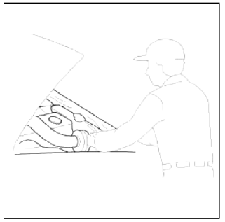
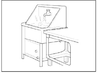
Protection Of The Vehicle
Always be sure to cover fenders, seats, and floor areas before starting work.
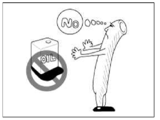
CAUTION
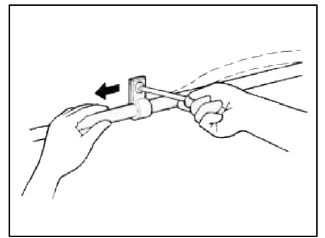
The support rod must be inserted into the hole near the edge of the hood whenever you inspect the engine compartment to prevent the hood from falling and causing possible injury.
Make sure that the support rod has been released prior to closing the hood. Always check to be sure the hood is firmly latched before driving the vehicle.
Preparation Of Tools And Measuring Equipment
Be sure that all necessary tools and measuring equipment are available starting work.
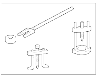
Special Tools
Use special tools when they are required.
Removal Of Parts
First find the cause of the problem and then determine whether removal or disassembly before starting the job.
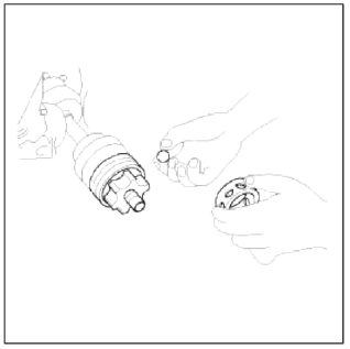
Disassembly
If the disassembly procedure is complex, requiring many parts to be disassembled, all parts should be disassembled in a way that will not affect then performance or external appearance.
1. Inspection of parts
Each part, when removed, should be carefully on suspected for malfunction, deformation, damage, and other problems.
2. Arrangement of parts
All disassembled parts should be carefully arranged for effective reassembly.
Be sure to separate and correctly identify the parts to be replaced hour those that will be used again.
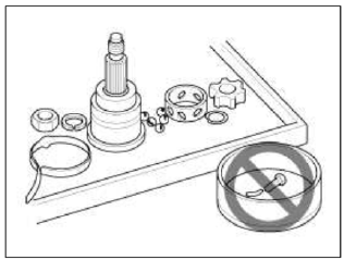
3. Cleaning parts for reuse
All parts to be used again should be carefully and thoroughly cleaned by an appropriate method.
Parts
When replacing parts, use KIA MOTORS genuine parts.

Replacement
Standard values, such as torques and certain adjustments, must be strictly observed in the reassembly of all parts.
If removed, the following parts should always be replaced with new ones.
1. Oil seals
2. Gaskets
3. O-rings
4. Lock washers
5. Cotter pins (split pins)
6. Plastic nuts
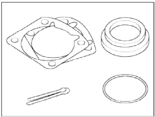
Depending on their location.
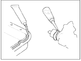
7. Sealant should be applied to gaskets.
8. Oil should be applied to the moving components of parts.
9. Specified oil or grease should be applied to the prescribed locations (oil seals, etc) before assembly.
Adjustment
Use gauges and testers to adjust correctly the parts to standard values correctly.
Electrical System
1. Be sure to disconnect the battery cable from the negative (-) terminal of the battery.
2. Never pull on the wires when disconnecting connectors.
3. Locking connectors will click when the connector is secure.
4. Handle sensors and relays carefully. Be careful not to drop them against other parts.
Rubber Parts And Tubes.
Always prevent gasoline or from touching rubber parts or tubing.
Measuring Body Dimensions
1. Basically, all measurements in this manual are taken with a tracking gauge.
2. When a measuring tape is used, check to be sure there is no elongation, twisting or bending.
3. For measuring dimensions, both projected dimensions and actual - measurement dimensions are used in this manual.
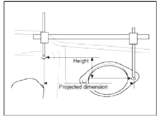
Dimensions Projected
1. These are the dimensions measured when the measurement points are projected from the vehicle's surface, and are the reference dimensions used for used for body alterations.
2. If the length of the tracking gauge probes is adjustable, measure it by lengthening one of two probes as long as the different value in height of the two surface.
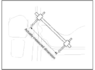
Measuring Actual Dimensions
1. These dimensions indicate the actual linear distance between measurement points, and are used as the reference dimensions when a tracking gauge is used for measurement.
2. First adjust both probes to the same length (A=A') before measurement.
NOTE
Check the probes and gauge itself to make sure there is no free play.
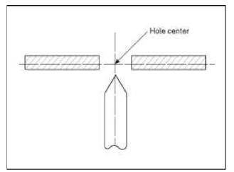
Measurement Point
Measurements should be taken at the center of the hole.
Checking Cables And Wires
1. Check the terminal for tightness.
2. Check terminals and wires for corrosion from battery electrolyte, etc.
3. Check terminals and wires for open circuits.
4. Check wire insulation and coating for damage, cracks and degrading.
5. Check the conductive parts of terminals for contact with other metallic parts (vehicle body and other parts).
6. Check grounded parts to verify that there is complete continuity between their attaching bolt(s) and the vehicle's body.
7. Check for incorrect wiring.
8. Check that the wiring is so clamped to the prevent contact with sharp corners of the vehicle body, etc. or hot parts (exhaust manifold, etc.)
9. Check that the wiring is clamped firmly to provide enough clearance from the fan pulley, fan belt and other rotating or moving parts.
10. Check that the wiring has a little space so that it can vibrate between fixed and moving parts such as the vehicle body and the engine.
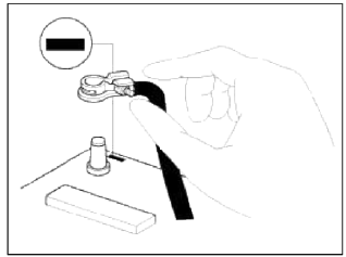
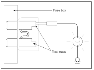
Check Fuses
A blade type fuse test taps provided to allow checking the fuse itself without removing if from the fuse box. The fuse is good if the test lamp lights up when one lead is connected to the test taps (one at a time) and the other lead is grounded. (Turn the ignition switch so that the fuse circuit becomes operative)
READ NEXT:
 Servicing The Electrical System
1. Prior to servicing the electrical system, be sure to turn off the ignition
switch and disconnect the battery ground
cable.
NOTE
In the course of MFI or ELC system diagnosis, when the battery c
Precautions For Catalytic Converter
CAUTION
If a large amount of unburned gasoline flows into the converter, it may
overheat and create a fire hazard. To
prevent this observe the following precautions and explain them to your
cust
SEE MORE:
Spot welding
1. Commercial spot welding machines do not perform
as well as the machines used in the manufacturing
process. When spot welding, increase the number
of spot welds by 30% (1.3 times the original number
of welds).
2. When spot welding, weld in the middle of the joint.
Spot welding on the
General Information
Specifications
Specifications
Tightening Torques
Repair procedures
Compression Pressure Inspection
NOTE
If the there is lack of power, excessive oil consumption or poor fuel
economy, measure the compression pressure.
1. Warm up and stop engine.
Allow the engine
Content
- Home
- Kia Sportage - Fifth generation (NQ5) - (2022-2026) - Owner's Manual
- Kia Sportage - Second generation (JEKM) (2005-2015) - Body Workshop Manual
- Kia Sportage Third generation (SL) - (2011-2016) - Service and Repair Manual
- Sitemap
- Top articles
