Kia Sportage: Overhead Console Lamp | Hazard Lamp Switch
Repair procedures
Inspection
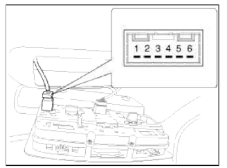
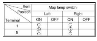
Remove the overhead console lamp assembly then check for continuity between terminals. If the continuity is not as specified, replace the map lamp switch.
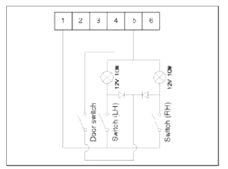
- Ground
- -
- -
- Door (-)
- Battery (+)
- -
Removal
1. Disconnect the negative (-) battery terminal.
2. Remove the overhead console lamp assembly.
(Refer to the BD group - "Roof trim")
3. Remove the overhead console bulb (B) after disconnecting the panoramaroof switch connector and lamp connector (A).
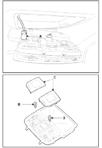
4. When replacing the bulb only, release the lens (C) cover from the roof without removing the overhead console lamp assembly.
Installation
1. Install the bulbs and connect the connectors.
2. Install the overhead console lamp assembly.
Hazard Lamp Switch
Repair procedures
Removal
1. Disconnect the negative (-) battery terminal.
2. Remove the center fascia panel (A).
(Refer to BE group - "Audio unit")
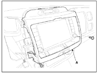
NOTE
Take care not to damage and scratch the center fascia panel and its related parts.
Apply the protective tapes to the center fascia panel and its related parts.
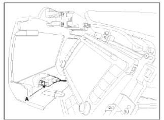
3. Disconnect the hazard switch unit connector (A).
4. If the hazard lamp switch is not as specified, replace it carefully and take care not to damage the hook (A).
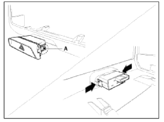
Installation
1. Connect the hazard switch connector.
2. Install the hazard switch assembly to the center fascia panel.
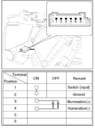
Inspection
1. Operate the switch and check for continuity between terminals with an ohmmeter.
READ NEXT:
 Rheostat | Front Fog Lamps | License Lamps
Repair procedures
Inspection
1. Disconnect the negative (-) battery terminal.
2. Remove the crash pad lower panel.
(Refer to the BD group - "Crash pad")
3. Remove the crash pad si
SEE MORE:
Electrical Equipment (U.S. only)
The electrical system of your vehicle is
designed to perform under all reasonably
expected operating conditions.
However, before any additional electrical
equipment is installed in your vehicle,
consult an Authorized Kia Dealer, in
order to ensure that you do not void
your warranty.
Cert
Waxing
Wax the vehicle when water will no longer
bead on the paint.
Always wash and dry the vehicle before
waxing. Use a good quality liquid or
paste wax, and follow the manufacturer's
instructions. Wax all metal trim to
protect it and to maintain its luster.
Removing oil, tar, and similar m
Content
- Home
- Kia Sportage - Fifth generation (NQ5) - (2022-2026) - Owner's Manual
- Kia Sportage - Second generation (JEKM) (2005-2015) - Body Workshop Manual
- Kia Sportage Third generation (SL) - (2011-2016) - Service and Repair Manual
- Sitemap
- Top articles
