Kia Sportage: PDM Relay Box
Components and Components Location
Components
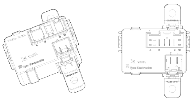
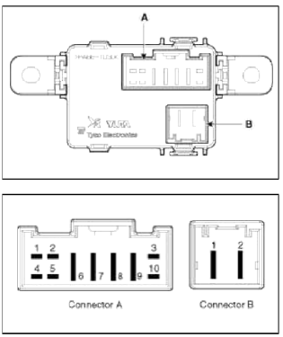
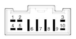 Connector A (10 pins)
- Smart key unit
- -
- Ground
- Smart key unit
- -
- ACC
- Battery power (IGN-1)
- IGN-1
- -
- Smart key unit
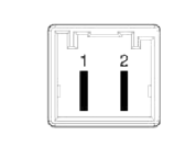 Connector Ð’ (2 pins)
- IGN-2
- Battery power (IGN-2)
Description and Operation
Description
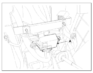
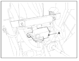
The PDM relay (A) is united with IG1, IG2 and ACC relays and installed in the lower center fascia panel.
Repair procedures
Removal
PDM Relay
1. Disconnect the negative (-) battery terminal.
2. Remove the floor console assembly.
(Refer to BD group - "Console")
3. Remove the PDM relay box (A) after loosening the bolts (2EA) and disconnecting the connector.
Installation
1. Install the PDM relay box.
2. Install the floor console assembly.
3. Connect the battery (-) cable.
Inspection
IG2 Relay
Check for continuity between the terminals.
1. There should be continuity between the No.1 and No.2 terminals in the Ð’ connector when power and ground are connected to the No.3 and No.4 terminals in the A connector.
2. There should be no continuity between the No.1 in the Ð’ and No.2 terminals in the Ð’ terminals when power is disconnected.
IG1 Relay
Check for continuity between the terminals.
1. There should be continuity between the No.7 and No.8 terminals in the A connector when power and ground are connected to the No.3 and No.10 terminals in the A connector.
2. There should be no continuity between the No.7 in the A and No.8 terminals in the A terminals when power is disconnected.
ACC Relays
Check for continuity between the terminals.
1. There should be continuity between the No.7 and No.6 terminals in the A connector when power and ground are connected to the No.1 and No.3 terminals in the A connector.
2. There should be no continuity between the No.7 in the A and No.6 terminals in the A terminals when power is disconnected.
READ NEXT:
 Components and Components Location | Instrument Cluster
Component Location
Cluster assembly
Seat belt switch
Vehicle speed sensor
Engine coolant temperature sender
Oil pressure switch
Brake fluid level warning swit
SEE MORE:
Intercooler
Components and
Components Location
Components
Recirculation hose
Intercooler inlet hose & pipe
assembly
Intercooler outlet hose & pipe
assembly
Intercooler mounting bracket
Intercooler upper mounting insulator
Intercooler
Intercooler lower mounting insulator
Blind-Spot View Monitor (BVM)
Blind-Spot View Monitor settings
Blind-Spot View Monitor (BVM) (if equipped)
Left side
Right side
Blind-Spot View Monitor displays the
rear blind spot area of the vehicle in the
cluster when the turn signal is turned on
to help safely change lanes.
Detecting sensor
SVM-side vie
Content
- Home
- Kia Sportage - Fifth generation (NQ5) - (2022-2026) - Owner's Manual
- Kia Sportage - Second generation (JEKM) (2005-2015) - Body Workshop Manual
- Kia Sportage Third generation (SL) - (2011-2016) - Service and Repair Manual
- Sitemap
- Top articles
