Kia Sportage: CVVT Oil Temperature Sensor (OTS)
Description and Operation
Description
Continuous Variable Valve Timing (CVVT) system advances or retards the valve tuning of the intake and exhaust valve in accordance with the ECM control signal which is calculated by the engine speed and load.
By controlling CWT , the valve over-lap or under-lap occurs, which makes better fuel economy and reduces exhaust gases (NOx, HC) and improves engine performance through reduction of pumping loss, internal EGR effect, improvement of combustion stability, improvement of volumetric efficiency, and increase of expansion work.
This system consist of
- the CVVT Oil Control Valve (OCV) which supplies the engine oil to the cam phaser or runs out the engine oil from the cam phaser in accordance with the ECM PWM (Pulse With Modulation) control signal.
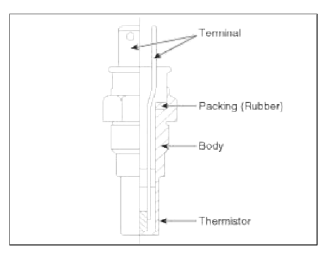
- the CVVT Oil Temperature Sensor (OTS) which measures the engine oil temperature,
- and the Cam Phaser which varies the cam phase by using the hydraulic force of the engine oil.
The engine oil getting out of the CVVT oil control valve varies the cam phase in the direction (Intake Advance/Exhaust Retard) or opposite direction (Intake Retard/Exhaust Advance) of the engine rotation by rotating the rotor connected with the camshaft inside the cam phaser.
Specifications
Specifications
Schematic Diagrams
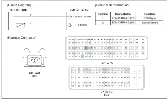
Circuit Diagram
Repair procedures
Inspection
1. Turn the ignition switch OFF.
2. Disconnect the OTS connector.
3. Remove the OTS.
4. After immersing the thermistor of the sensor into engine coolant, measure resistance between the OTS terminals 1 and 2.
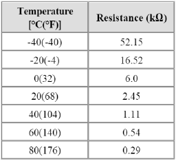
5. Check that the resistance is within the specification.
Specification: Refer to "Specification"
Removal
1. Turn the ignition switch OFF.
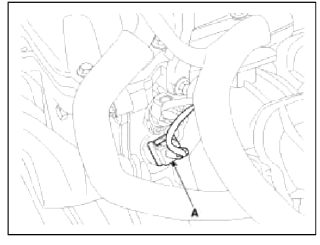
2. Disconnect the OTS connector (A).
3. Remove the OTS.
Installation
1. Installation is reverse of removal.
READ NEXT:
 Accelerator Position Sensor (APS) | Fuel Tank Pressure Sensor (FTPS)
Description and Operation
Description
Accelerator Position Sensor (APS) is installed on the accelerator pedal module and detects the rotation angle of the accelerator pedal. The APS is one of
Injector
Description and Operation
Description
Based on information from various sensors, the ECM can calculate the fuel
amount to be injected. The fuel injector
is a solenoid-operated valve and the
SEE MORE:
Interior light adjustment switch
The brightness of the instrument panel
illumination is changed by pressing the
illumination control button ("+" or "-")
when the ignition switch or ENGINE
START/STOP button is ON, or the tail
lamps are turned on.
WARNING
Never adjust the instrument cluster
while drivi
General Information | Front Body
General
1. Basically, all measurements in this manual are taken with a tracking gauge.
2. When a measuring tape is used, check to be sure there is no elongation, twisting or bending.
3. For measuring dimensions, both projected dimension and actual-measurement dimension are used in this m
Content
- Home
- Kia Sportage - Fifth generation (NQ5) - (2022-2026) - Owner's Manual
- Kia Sportage - Second generation (JEKM) (2005-2015) - Body Workshop Manual
- Kia Sportage Third generation (SL) - (2011-2016) - Service and Repair Manual
- Sitemap
- Top articles
