Kia Sportage: Rear Parking Assist System Control Unit
Specifications
Specifications
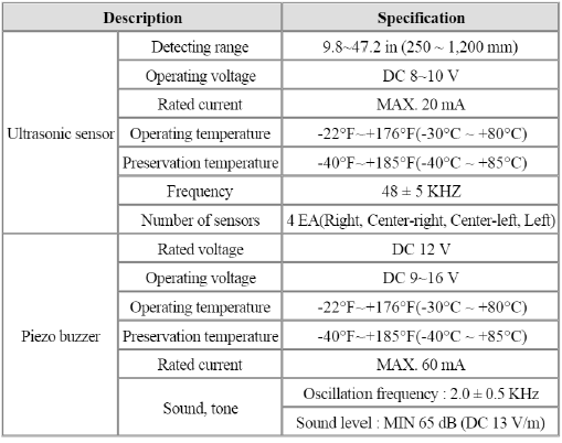
The BCM contains the rear parking assist system function.
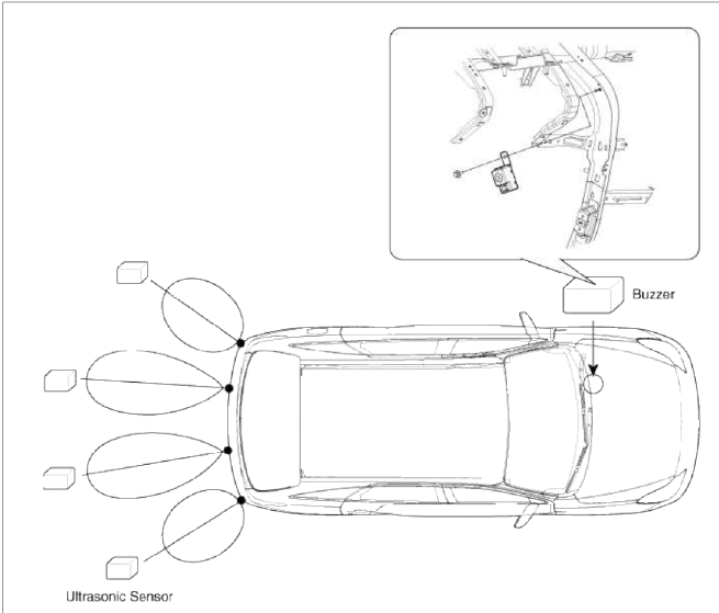
Components and Components Location
Component Location
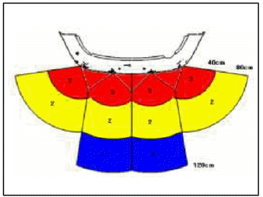
- First alarm: Object comes near to the sensor located at the rear of vehicle, within 81-120cm +- 15cm
- Second alarm: Object comes near to the sensor located at the rear of vehicle, within 41-80cm +- 10cm
- Third alarm: Object comes near to the sensor located at the rear of vehicle, within 40cm +- 10cm
Description and Operation
Description
When reversing, the driver is not easy to find objects in the blind spots and to determine the distance from the object. In order to provide the driver safety and convenience, back warning system will operate upon shifting to "R" Ultrasonic sensor will emit ultrasonic wave rearward and detect the reflected wave.
Control unit (BCM) will calculate distance to the object using the sensor signal input and output buzzer alarm in three steps (first, second and third alarm).
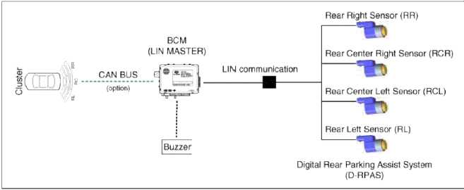
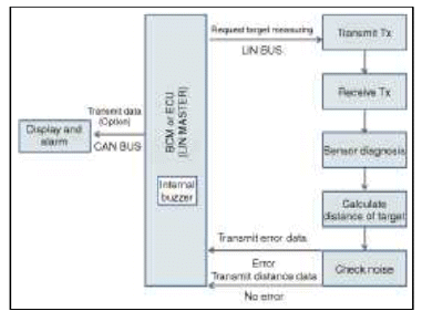
Block Diagram
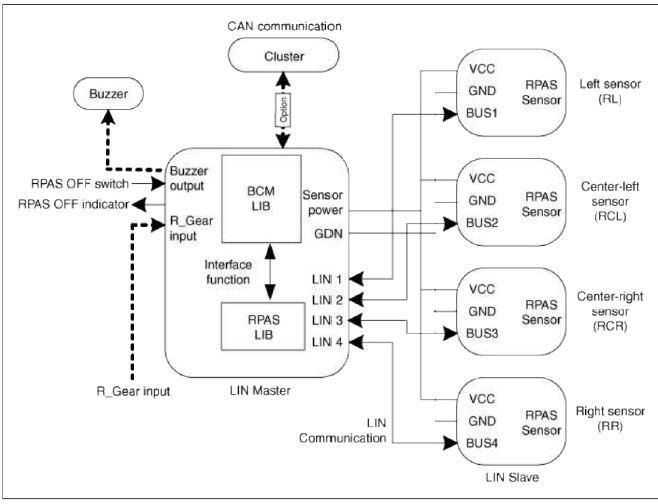
Operation
System Operation
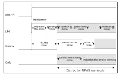
Initial Mode
1. RPAS checks the ID and Reference (shaping table) during the initialization using LIN communication.
2. If sensor ID or sensor parameter is same with expected value, RPAS system is initialized within 500ms after turning IGN1 and shifting R gear.
3. If Sensor ID or sensor parameter is different with expected value, initial mode can take about 1.2 second after turning IGN1 and shifting R gear because of teaching sensor ID or sensor parameter.
4. RPAS executes the diagnosis of each sensor dining the initialization.
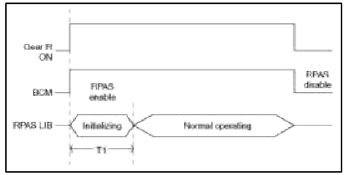
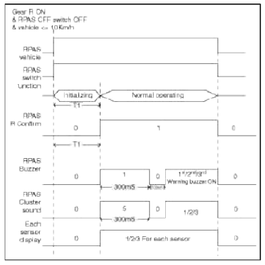
T1: RPAS initializing time
- In case of sensor teaching, T1 : within 1.2 second
- In case of normal condition, T1 : 500ms +- 10%
Normal Mode
Normal mode of RPAS can divide as two steps.
First step is a mode to inform the driver of the RPAS system ON and diagnosis results which is executed dining the initialization.
Second step is the obstacle detection mode to give driver warning when detecting the obstacle.
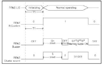
1. Driver info mode for RPAS ON
- If there aren't any diagnosis messages from sensors, the normal RPAS ON sound with ON-period 300ms warn after initializing time since R gear is shifted. The obstacle detection warning starts after the delay of 100ms since finishing the normal RPAS ON warning sound.
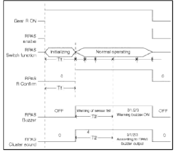
- If there are any failure sensor, "Warning of sensor fail" sound is
driven during the fixed period and if there is
any display unit, it displays the diagnosis.
Refer to the Diagnosis buzzer sound for more detail Information.
T1 : RPAS initializing tune
- In case of sensor teaching, T1 : within 1.2 second
- In case of normal condition, T1 : 500ms +- 10%
T2 : Refer to the spec for warning of fail
- "Diagnosis-buzzer" is driven only one time but the display unit continue to display the diagnosis according each failure sensor's location.
2. Obstacle detection mode
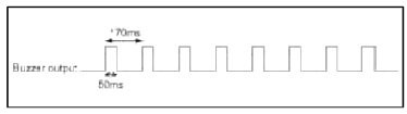
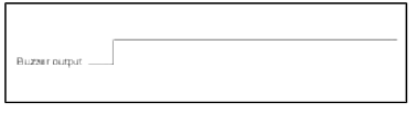
- There are 3 kinds of warning sound for detecting the obstacle, the 1st warning and the 2nd warning are the intermittent sound and the 3rd warning is the continuous sound.
- The vehicle speed for the operation of RPAS is below 10Km/h .
- There are 2 kinds of detection mode. One is for normal operating mode using normal 4 sensors. Even if any sensor is on failure condition, the RPAS system will be entered to degrade mode excepting a failure sensor.
- Operating procedure
Detection Area
1. Test condition - PVC pole (Diameter 75mm, Length 1m) & At the room temperature
2. Distance tolerance (measured at the front of sensor)
81 cm ~ 120 cm : +- 15 cm
41 cm ~ 80 cm : +- 10 cm
Below 40 cm : +- 10 cm
3. Below 30 cm may not be detected.
4. Sensing zone specification
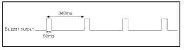
Sound pulse has a fixed duration.
Pause between pulses is related to the distance from the obstacle and is not variable.
Although the position of the obstacle is not moving dining sometime, the buzzer should keep warning. And although an obstacle that is currently warned is getting far, the buzzer should keep warning according to obstacle distance.
The warning sound is generated by the algorithm of ECU which measures the distance of the obstacle from the sensor.
The distance is divided into three detection ranges. Obstacles below 30cm from the sensor may not be detected.
Each Warning Zone Hysteresis Function for buzzer and display.
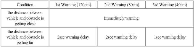
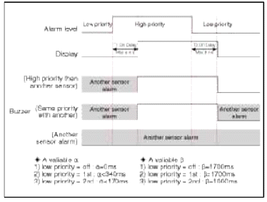
Warning method of RPAS
If RPAS sensor detects the obstacle, the acoustic device makes warning sound and the display module (Cluster) indicates each warning level as like followings.
RPAS sensor sends the distance data to BCM through LIN communication and BCM received the distance data from each sensor.
BCM has the responsibility of the acoustic function.
BCM has the responsibility of the gateway function that BCM sends the warning data to Cluster as like below timing diagram.
When change from a warning area to the different zone, after finishing one cycle of warning output, the next warning sound has to staid for different zone necessarily.
Timing Chart for RPAS Warning Sound
If Power is supplied to the system (turning IGN1 and shifting R gear), BCM checks the channel of each sensor and if no problems, the buzzer sound with turn-on period 300ms is generated after 500ms, but even if one sensor has a problem, the buzzer sound not for "Staid-buzzer of RPAS" but for "Diagnosis-buzzer of RPAS". The next action for Normal mode is like followings.
After R gear is aimed, the system operation is like followings.
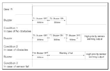
Time tolerance: +-10%
After R gear is disarmed, the system operation is like followings.
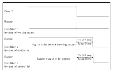
Time tolerance: +-10%
Sensor interval distance dividing alarm output specification
The condition logic is as below according to phase logic in priority. (In same sensor)
RPAS operation ranges according to distance are as below.
1. First alarm (81 cm ~ 120 cm)
2. Secondary alarm (41 cm ~ 80 cm)
3. Third alarm (40 cm or less)
4. Failure alarm cycle
When the system starts and sensor has errors, the warning sound as the sensor position is like following.
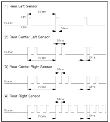
In the case that the multiple sensors have errors, the sequence of sensor's warning is like followings.
RL → RCL → RCR → RR
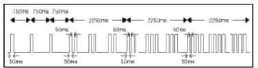
After the warning sound for diagnosis is generated, the other normal sensors execute the normal function such as the detection and the transmission of distance data.
NOTE
1. Time tolerance of the above waveform: Time +- 10%
2. At nearer distance than 30cm, detection may not occur.
3. Alarm will be generated with vehicle reversing speed 10km/h or less.
4. For moving target, maximum operation speed shall be target approach speed of 10km/h.
5. When the vehicle or the target is moving, sequential alarm generation or effective alarm may be failed.
6. False alarm, or failure of the alarm to trigger may occur in the following conditions.
- Irregular road surface, gravel road, reversing toward glass.
- Horn motor cycle engine noise, large vehicle air brake, or other object generating ultrasonic wave is near.
- When a wireless transmitter is used near to the sensor.
- Din on the sensor.
- Sequential alarm may not occur due to the reversing speed or the target shape.
Method of error handling
â– LIN BUS Off error
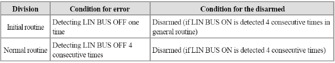
Remarks
1. LIN BUS OFF means no response from sensors when BCM send request to sensors.
2. In the case that error happens to the initial routine, diagnosis warning sound + display for error.
3. In the case that error happens to the Normal routine, the only display for error.
4. If error happens to the direct condition of each sensor, after that, error is transmitted at the indirect condition (sensor side).
â– In the case of sensor error
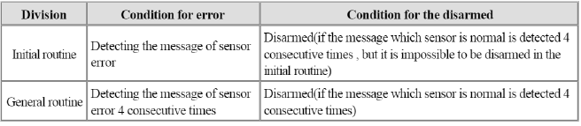
Remarks
1. In the case of fault counting output message or signal with last valid should be transmitted.
2. In the case that error happens to the initial routine, diagnosis warning sound + display for error.
3. In the case that error happens to the general routine, the only display for error.
READ NEXT:
 Ultrasonic Sensor
Components and
Components Location
Components Location
Repair procedures
Removal
1. Lift up the vehicle.
(Refer to GI group - "Lift and support points")
2. Remove the rear b
Components and Components Location | Description and Operation
Component Location
Start Stop Button (SSB)
FOB key holder
FOB key
Tailgate switch
Smart key unit
RF receiver
BCM (Body Control Module)
Interior anten
SEE MORE:
Description and Operation, Specifications, Troubleshooting, Schematic Diagrams | Components and Components Location
Description and Operation
Description
Emissions Control System consists of thee major systems.
The Crankcase Emission Control System prevents blow-by gas from releasing into the atmosphere. This system recycles gas back into the intake manifold (Closed Crankcase Ventilation Type)
Tire sidewall labeling
This information identifies and
describes the fundamental characteristics
of the tire and also provides
the Tire Identification Number (TIN)
for safety standard certification.
The TIN can be used to identify the
tire in case of a recall.
Manufacturer or brand name
Manufacturer or Br
Content
- Home
- Kia Sportage - Fifth generation (NQ5) - (2022-2026) - Owner's Manual
- Kia Sportage - Second generation (JEKM) (2005-2015) - Body Workshop Manual
- Kia Sportage Third generation (SL) - (2011-2016) - Service and Repair Manual
- Sitemap
- Top articles
