Kia Sportage: Smart key unit
Components and Components Location
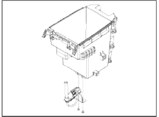
Components
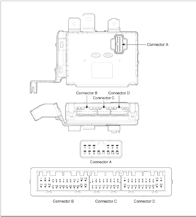
Connector Pin Information
Connector A (14 Pin)
- Ground 1
- A_ACC
- A_IGN2
- A_IGN1
- VBAT_CPU
- VBAT_LOAD
- Ground 2
- -
- O_Exterior buzzer
- O_ACC Relay
- O_IGN1 Relay
- O_IGN2 Relay
- O_Starter Relay
- -
Connector Ð’ (26 Pin)
- -
- L_Driver lock
button,
L_Driver toggle button - -
- -
- -
- L_SSB_Switch1
- F_Wheel vehicle
- L_SSB_Switch2
- -
- -
- -
- B_CAN_H
- B_CAN_L
- -
- L_Passenger lock
button,
L_Passenger toggle button - -
- -
- -
- L_Fob input
- F_RPM
- L_Start Feedback
- -
- -
- -
- -
- L_Tailgate Switch
Connector C (16 Pin)
- C_CAN_L
- C_CAN_H
- -
- O_Holder illumination
- -
- Diagnostic К
- L_Brake switch
- Immobilizer data
- RF_COM
- EMS_COM
- -
- -
- L_Stop lamp fuse
- -
- L P shift, L Clutch switch
- Immobilizer clock
Connector D (22 Pin)
- Immobilizer warning lamp
- O_SSB_LED_AMBER
- O_SSB_illumination power
- O_Interior antenna 2 ground
- O_Interior antenna 1 ground
- -
- -
- O_Interior antenna 3 power
- O_Buinper antenna power
- O_Passenger side antenna power
- O_Driver side antenna power
- -
- O_SSB_LED_Blue
- O_SSB_illumination ground
- O_Interior antenna 2 power
- O_Interior antenna 1 power
- -
- -
- O_Interior antenna 3 ground
- O_Bumper antenna ground
- O_Passenger side antenna ground
- O_Driver side antenna ground
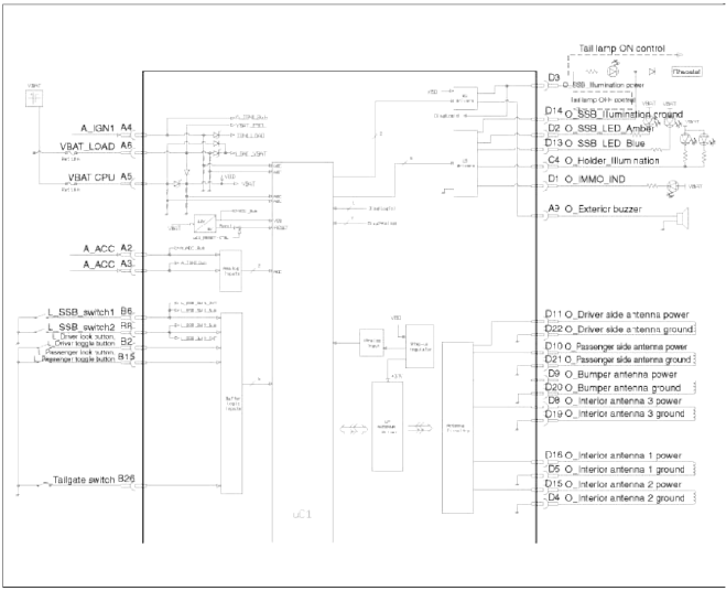
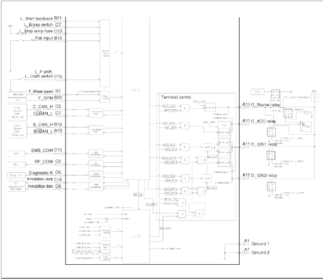
Schematic Diagrams
Circuit Diagram
Repair procedures
Removal
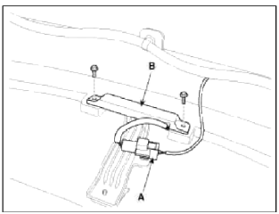
Smart Key Unit
1. Disconnect the negative (-) battery terminal.
2. Remove the glove box.
(Refer to the BD group - "Crash pad")
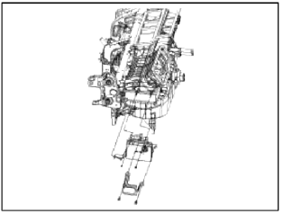
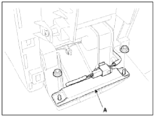
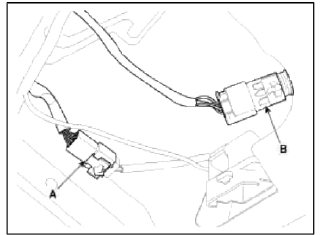
3. After disconnecting the smart key unit connectors (A), loosen the smart key unit mounting nuts (2EA), and remove the smart key unit (B).
[USA]
![[Canada]](images/books/1921/8/index%20115.png)
[Canada]
RF Receiver
1. Disconnect the negative (-) battery terminal.
2. Remove the floor console.
(Refer to the BD group - "Console")
3. Disconnect the RF receiver connector and remove the RF receiver mounting screws. Remove the RF receiver.
Interior 1 Antenna
1. Disconnect the negative (-) battery terminal.
2. Remove the floor console.
(Refer to the BD group - "Console")
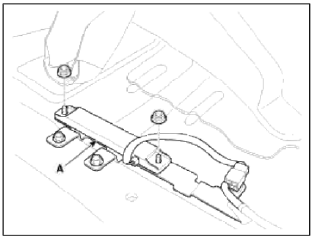
3. After loosening the antenna nuts (2EA) and connector (B). remove the interior 1 antenna (A).
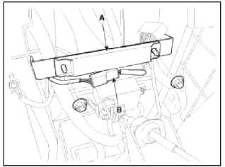
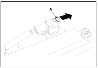
NOTE
Release the connector lock (A) as indicated by the arrow, and then push-down the lock.
Make sure the connector is locked completely when installing.
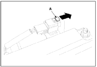
Interior 2 Antenna
1. Disconnect the negative (-) battery terminal.
2. Remove the floor console rear panel (A) using the appropriate tool.
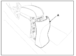
NOTE
Take care not to damage and scratch the floor console rear panel and its related parts.
Take care not to damage the hook when removing the floor console rear panel.
3. After loosening the antenna nuts (2EA) and connector, remove the interior 2 antenna (A).
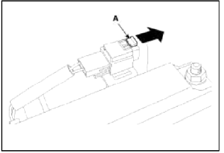
NOTE
Release the connector lock (A) as indicated by the arrow, and then push-down the lock.
Make sure the connector is locked completely when installing.
Interior 3 Antenna
1. Disconnect the negative (-) battery terminal.
2. After loosening the mounting bolts, then remove the rear seat assembly.
(Refer to the BD group - "Rear seat")
3. Remove the luggage side trim (RH, LH), and then remove the rear floor carpet.
(Refer to the BD group - "Interior trim")
4. After loosening the antenna nuts (2EA) and connector (A), remove the interior 3 antenna (B).
NOTE
Release the connector lock (A) as indicated by the arrow, and then push-down the lock.
Make sure the connector is locked completely when installing.
Exterior Bumper Antenna
1. Disconnect the negative (-) battery terminal.
2. Lift the vehicle up using the lift.
(Refer to the GI group - "Lift And Support Points")
3. Remove the rear bumper.
(Refer to the BD group - "Rear bumper")
4. Disconnect the antenna connector (A) on the center of rear bumper.
5. After loosening the screws (2EA), remove the exterior bumper antenna (B).
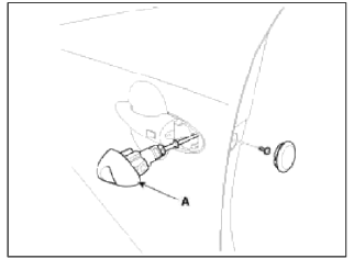
Buzzer
1. Disconnect the negative (-) battery terminal.
2. Remove the front left fender.
(Refer to the BD group - "Fender")
З. Disconnect the connector, then remove the buzzer (A).
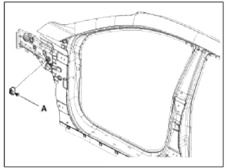
Door Outside Handle
1. Disconnect the negative (-) battery terminal.
2. Disconnect the connector after removing the door trim.
(Refer to the BD group - "Front door")
3. After loosening the mounting bolt, then remove the key holder (A).
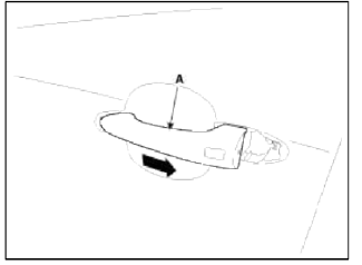
4. Remove the outside handle (A) by sliding it rearward.
Tailgate Switch
1. Disconnect the negative (-) battery terminal.
2. Remove the tailgate trim.
(Refer to the BD group - "Tailgate trim")
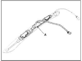
3. Disconnect the license lamp and tailgate switch connector (A). Disconnect the back warning camera connector (B).
4. Remove the screws (2EA) and clips (4EA). Remove the tailgate garnish (A).
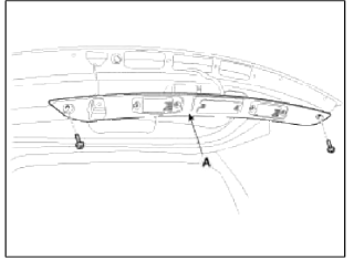
5. Loosen the tailgate outside handle mounting screw. Remove the outside handle and license lamp (A).
Inspection
Smart Key Unit
- Refer to BE group - Smart key system - inspection / self diagnosis with scan tool.
Smart Key Switch
- Refer to BE group - Smart key system - inspection / self diagnosis with scan tool.
Antenna
- Refer to BE group - Smart key system - inspection / self diagnosis with scan tool.
Tailgate Switch
1. Check for continuity between the tailgate switch terminals.
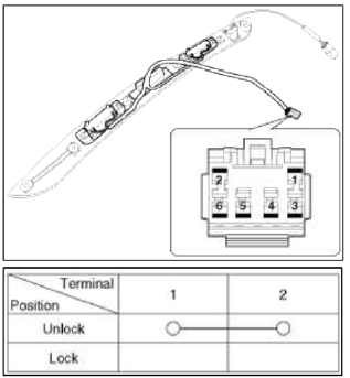
2. If needed, replace the switch.
Installation
Smart Key Unit
1. Install the smart key unit.
2. Install the smart key unit mounting nuts, and then connect the connector.
3. Install the glove box.
4. Install the negative (-) battery terminal and check the smart key system.
RF Receiver
1. Install the RF receiver.
2. Install the floor console.
3. Install the negative (-) battery terminal and check the smart key system.
Interior 1 Antenna
1. Install the interior 1 antenna.
2. Install the floor console.
3. Install the negative (-) battery terminal and check the smart key system.
Interior 2 Antenna
1. Install the interior 2 antenna.
2. Install the floor console rear cover after connecting the connector.
3. Install the negative (-) battery terminal and check the smart key system.
Interior 3 Antenna
1. Install the interior 3 antenna.
2. Install the rear seat assembly.
3. Install the negative (-) battery terminal and check the smart key system.
Exterior Bumper Antenna
1. Install the exterior bumper antenna.
2. Install the negative (-) battery terminal and check the smart key system.
Buzzer
1. Install the buzzer.
2. Install the front left fender.
3. Install the negative (-) battery terminal and check the smart key system.
Door Outside Handle
1. Install the outside handle.
2. Install the door trim.
3. Install the negative (-) battery terminal and check the smart key system.
Tailgate Switch
1. Install the tailgate switch.
2. Install the tailgate garnish.
3. Install the tailgate trim.
4. Install the negative (-) battery terminal and check the smart key system.
READ NEXT:
 Specifications, Components and Components Location | Description and Operation
Specifications
Specification
Components and Components Location
Component Location (1)
Hood switch
Burglar horn
RKE receiver
BCM (Body Control Module)
Fro
SEE MORE:
Output Speed Sensor
Description and Operation
Description
The output speed sensor is a vital unit that measures the rate of rotation of
the transaxle's turbine shaft and output
shaft, and delivers the readings to the TCM. The sensor provides critical input
data that's used in feedback control,
dam
Navigation-based Smart Cruise Control limitations
Navigation-based Smart Cruise Control
may not operate normally under the following
circumstances:
The navigation is not working properly
Map information is not transmitted
due to infotainment system's abnormal
operation
Speed limit and road information in
the navigation is not up
Content
- Home
- Kia Sportage - Fifth generation (NQ5) - (2022-2026) - Owner's Manual
- Kia Sportage - Second generation (JEKM) (2005-2015) - Body Workshop Manual
- Kia Sportage Third generation (SL) - (2011-2016) - Service and Repair Manual
- Sitemap
- Top articles
