Kia Sportage: Specifications, Components and Components Location | Description and Operation
Specifications
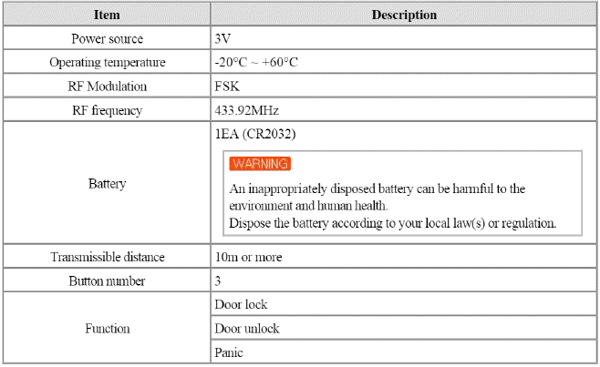
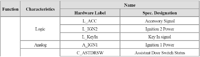
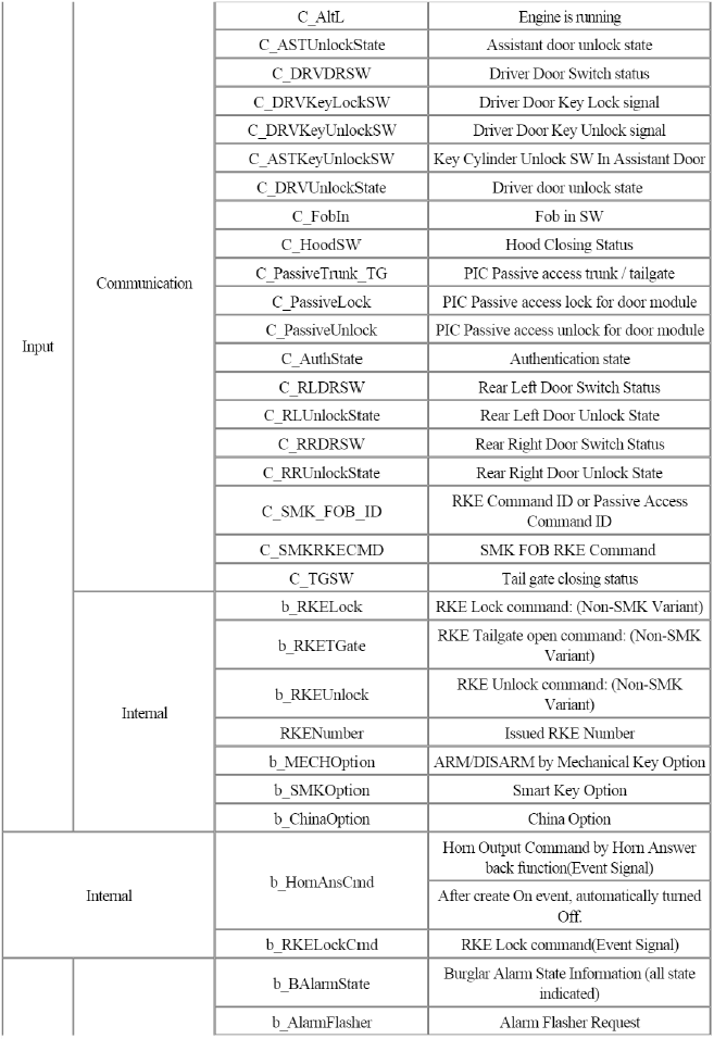
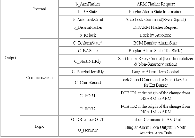
Specification
Components and Components Location
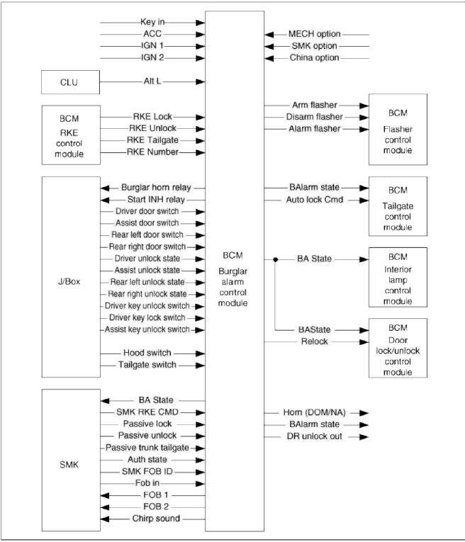
Component Location (1)
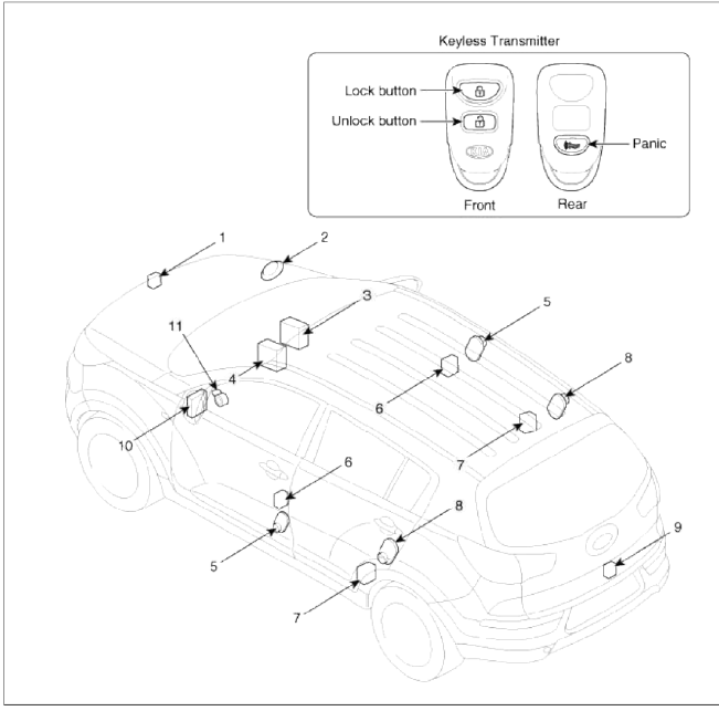
- Hood switch
- Burglar horn
- RKE receiver
- BCM (Body Control Module)
- Front door switch
- Front door lock actuator & switch
- Rear door lock actuator & switch
- Rear door switch
- Tailgate release switch
- SJB (Smart Junction Box)
- Key warning switch
Component Location (2)
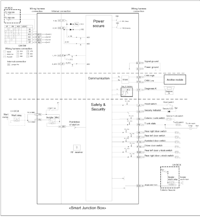
Schematic Diagrams
Circuit Diagram
Description and Operation
Description
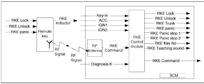
Remote Keyless Entry System
The described function is a radio-frequency remote control for central doors locking / unlocking, trunk release and Panic activity of art automotive vehicle without using a mechanical key.
Tins system confirms successful (un-)locking through flash light or/and a hour signal.
This will be a part of the equipment of vehicles in case of the Non-SMK variant.
- Transmitter with 3 buttons (door locking, door unlocking, and panic).
- Receiver is integrated in the BCM.
- BCM, control runt in which remote control decoding is done.
RF System Function Data Flow
Key (button) Operation
1. New button event is detected in the condition of "button-off".
2. Chattering time of Lock/Unlock buttons is 100 ms and Trunk button have 1s chattering time and Panic button is 500ms.
3. If a button switch is off before determining the button switch value (100ms), RF transmission is stopped.
4. If more two buttons pressed simultaneously, older is rejected.
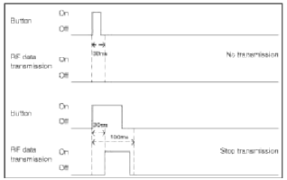
Key (button) Operation Abnormal Transmit Tuning Chart
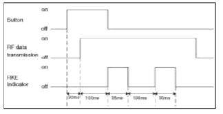
Indicator (LED)
Each transmitter has a red LED on the housing top. It indicates the transmission activity. The LED blinks same times with RF data First valid frame transmission times follow is "normal frame" case.
Normal frame cases are Lock frame, Unlock frame, Panic frame, Trunk frame, it is also valid case and first detection frame.
There is one exception to this rule, Panic Stop frame has to ignore for LED blinking.
If you want to know other cases, refer the figure in chapter for Validated Key (button) Input for Protection of Panic noise.
When RF Data is transmitted, the LED is blinked like below.
Receiver & BCM Function
Tins function describes the following features
- RKE Lock
- RKE Unlock
- RKE Panic
- RKE PanicStop 1/ RKE PanicStop2
- Memory order by RKE Lock
- Key Teaching
- Synchronization / Resynchronization
Key Teaching
Key Teaching is that BCM has the identification of remote key and Synchronization of rolling code between BCM and remote key.
1. Key Teaching with GDS Diagnostic Tool
- Key teaching Step refers to the Diagnostic Specification.
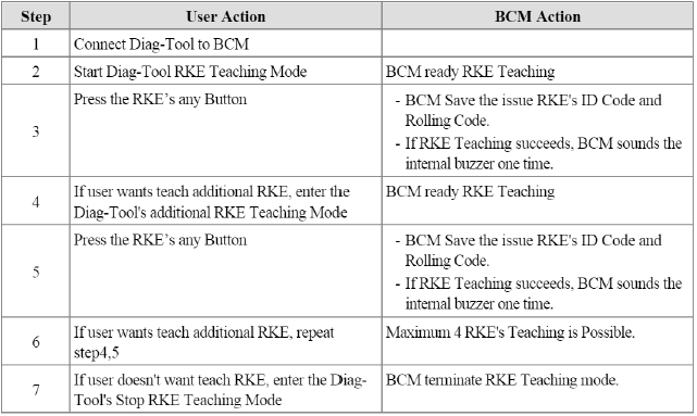
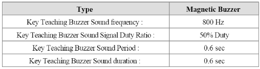
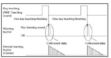
2. Key Teaching Sound
Only for information: (RKE teaching sound is described in Warning function specification)
- When each Key's teaching is ended, magnetic buzzer is operated, every one time.
- Key Teaching Buzzer Sound Characteristics
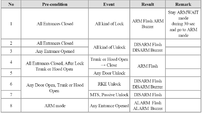
Burglar Alarm System
- The Burglar Alarm System is a function used to prevent or deter the unauthorized appropriation of the vehicle.
Theft prevention or Burglar Alarm function has been introduced to assert the ownership whenever the rightful owner is physically present. In an attempt to discourage theft, Burglar Alarm works by emitting high-volume sound (Horn) when triggered by circuit breach. This vehicle alarm is designed to be triggered by opening special switches (e.g. doors, hood, trunk open switch contacts)
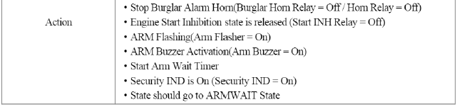
- This system also prevents the car from starting by disabling Starter relay if intrusion has been detected.
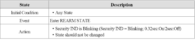
- To indicate that the vehicle is anti-theft protected a blinking indicator located at a visible area in the vehicle is provided (this is part of a theft preventive action).
The Alarm System function group consists of an Burglar Alarm function.
The Burglar Alarm offers a theft protection functions which.
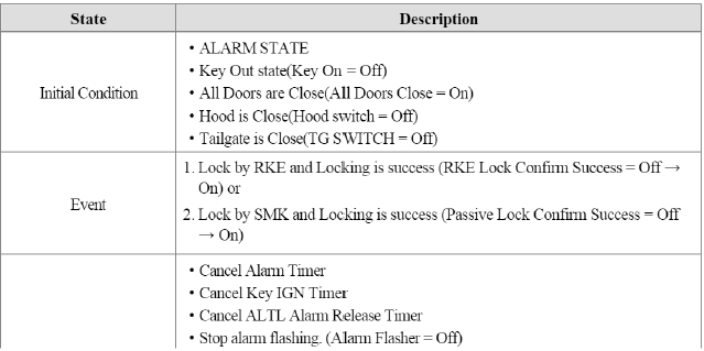
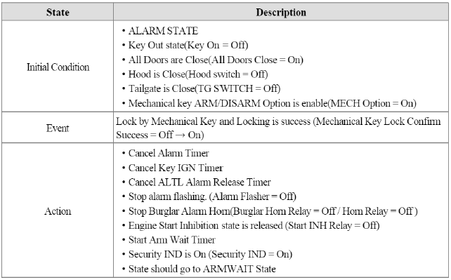
1. Armed by
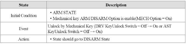
- Mechanical key lock switch in driver side door if Mechanical Option is set
- By RKE lock or SMK lock command
- All door lock and then all door closed if Mechanical Option is set
2. Triggers an alarm when
- Any doors open
- Hood open
- Trunk open by unknown event
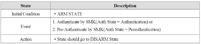
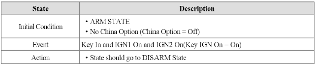
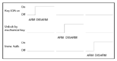
3. Disarmed by
- Turning the mechanical key unlock switch in driver side door if Mechanical Option is set
- By RKE unlock or SMK unlock command
Burglar Alarm Function Data Flow
Burglar Alarm Control Function
This function specification describes the following states of Burglar Alarm Control
- ARM Mode
- DISARM Mode
- ARMWAIT Mode
- ALARM Mode
- ARMHOLD Mode
- AutoLockTimer1 Mode
- AutoLockTinier2 Mode
- PRE ARM Mode
- REARM Mode
Function Description
Signal Activity
The Burglar Alarm System provides the function that shall inhibit the use of the vehicle when intrusion into the vehicle has been detected.
1. Burglar Alarm State is managed by the Burglar Alarm Control function for SMK, and is dependant on Burglar Alarm Control state as follows:
- Burglar Alarm State = 1: Burglar Alarm Control state is in ARM or ALARM or REARM or ARMWAIT
- Burglar Alarm State = 0: Burglar Alarm Control state is in DISARM or AUTOLOCKTIMER1 or AUTOLOCKTIMER2 or ARMHOLD or PREARM
2. At the time of sending on the CAN signal to ARM type state from DISARM type state, the BCM unit shall send the CAN signals FOB1 and FOB2 set versus the memorized Key fob ID number.
- If Key Number = 1 is sending, FOB1 = 1 otherwise FOB1 = 0
- If Key Number = 2 is sending, FOB2 = 1 otherwise FOB2 = 0
3. To make available to other internal BCM functions the current Burglar Alarm Control state.
4. Burglar Alarm State is updated each time the Burglar Alarm Control is changed of state.
Power Condition Activity
State by RESET Condition
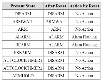
1. Reset means battery input restarted.
2. Only in ALARM State or REARM State, when reset is occurred, it is retried Alarm Flashing.
3. After reset, All timers should be reset.
State Description
Parameter Value
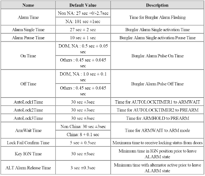

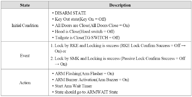
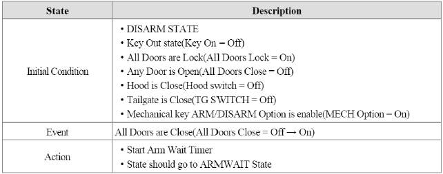
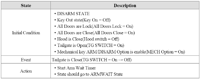
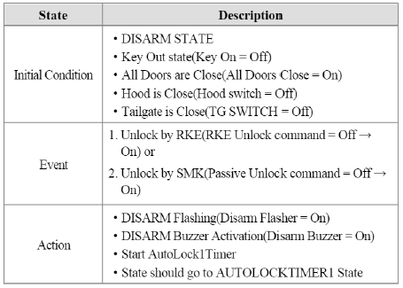
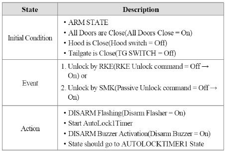
DISARM
1. DISARM to DISARM
Condition 1
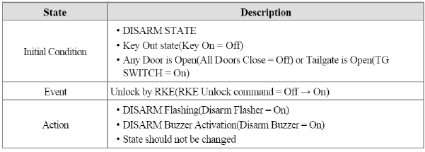
Condition 2
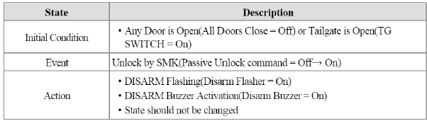
Condition 3
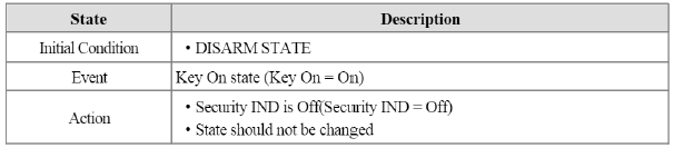
Condition 4
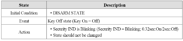
Т1 : 0.5 +- 0.05 sec, T2 : Arm Disarm buzzer duration
2. ARMWAIT to DISARM
Condition 1
Condition 2
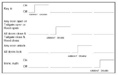
3. ARM to DISARM
Condition 1
Condition 2
Condition 3
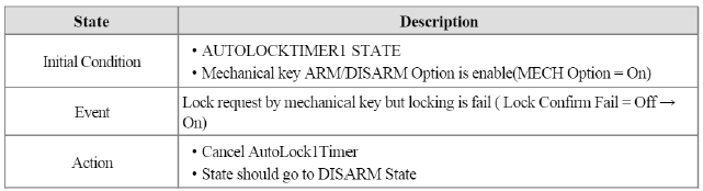
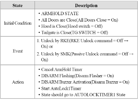
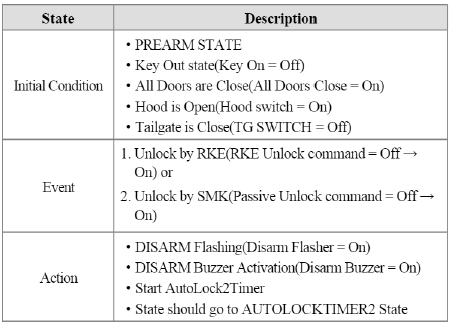
4. AUTO LOCK TIMER1 to DISARM
Condition 1

Condition 2
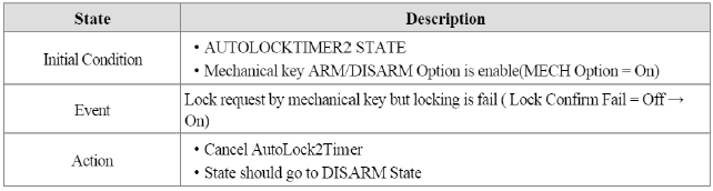
5. AUTO LOCK TIMER2 to DISARM
Condition 1
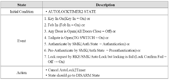
Condition 2
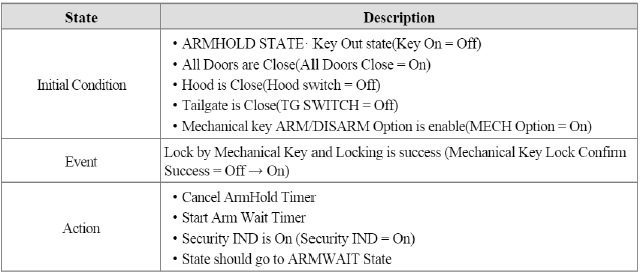
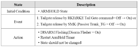
6. ARMHOLD to DISARM
Condition 1
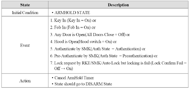
Condition 2
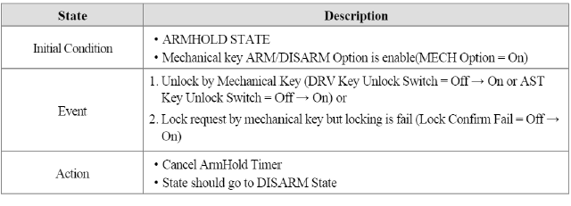
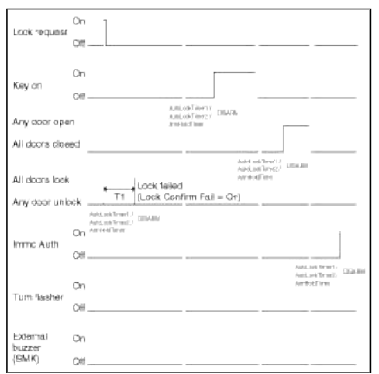
T1 : Lock fail confirm time
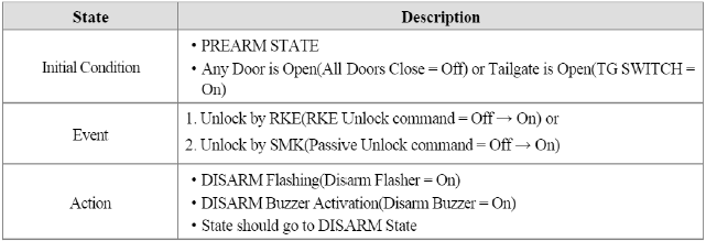
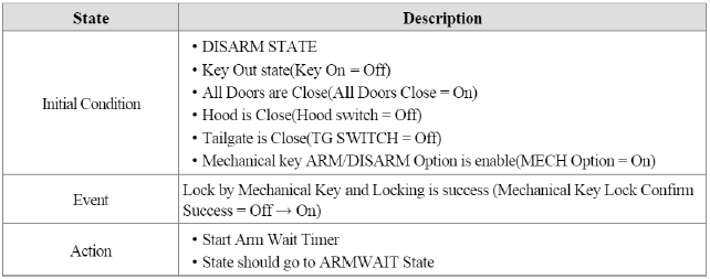
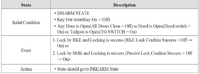
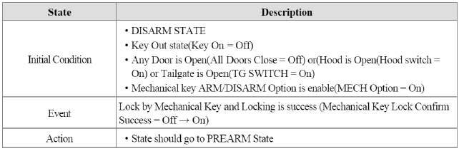
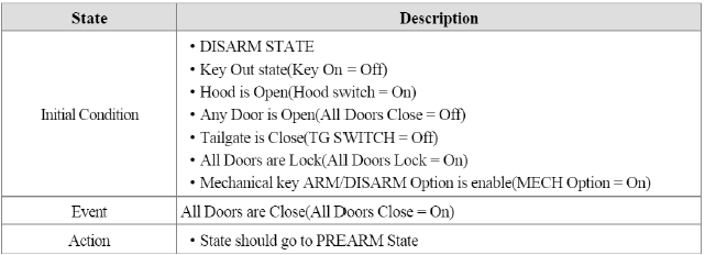
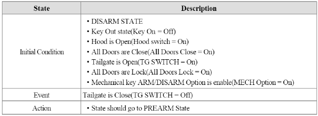
7. PREARM to DISARM
Condition 1
Condition 2
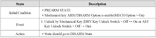
Condition 3
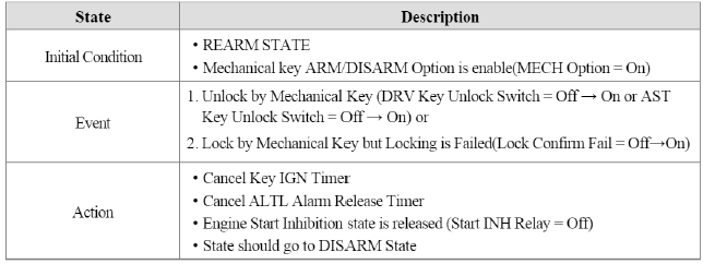
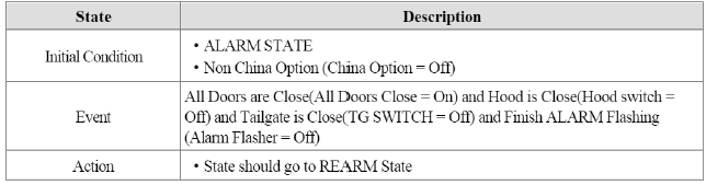
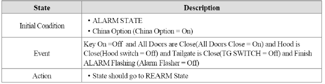
8. REARM to DISARM
Condition 1
Condition 2
Condition 3
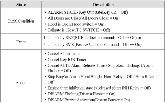
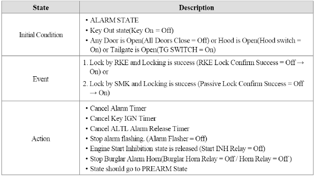
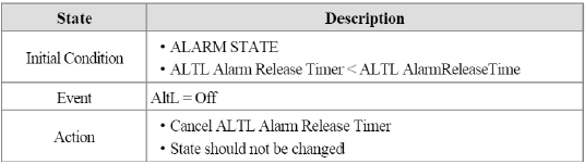
9. ALARM to DISARM
Condition 1
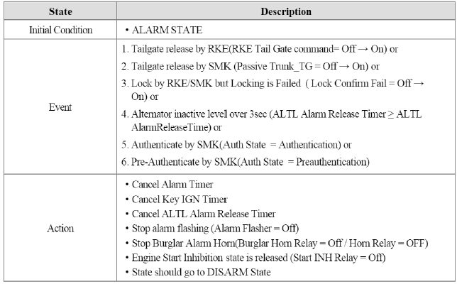
Condition 2
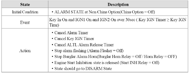
Condition 3
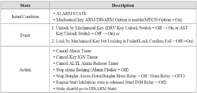
Condition 4
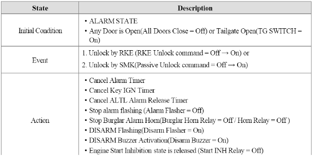

T1 : Lock fail confirm time, T2 : ALT L alarm release time
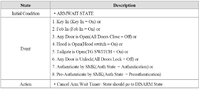
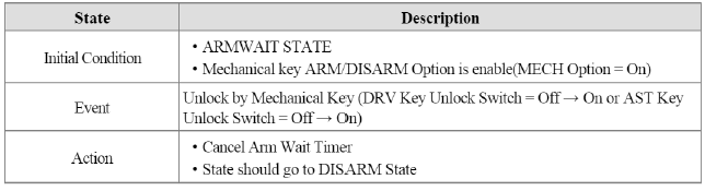
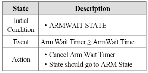
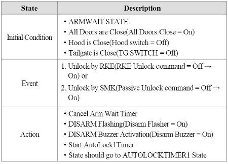
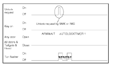
ARM WAIT
1. DISARM to ARMWAIT
Condition 1
Condition 2
Condition 3
Condition 4
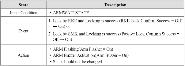
2. ARMWAIT to ARMWAIT
Condition 1
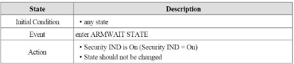
Condition 2
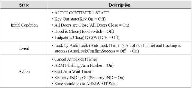
3. AUTO LOCK TIMER1 to ARMWAIT
Condition 1
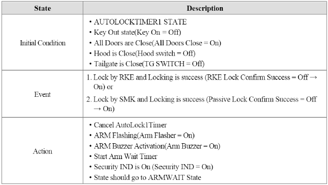
Condition 2
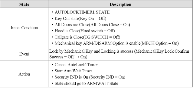
Condition 3
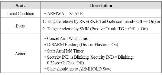
4. ARMHOLD to ARMWAIT
Condition 1
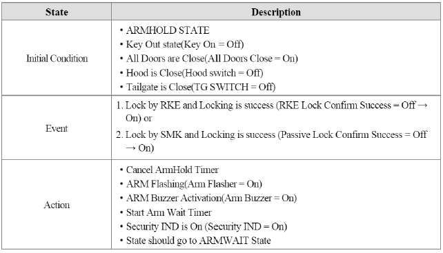
Condition 2
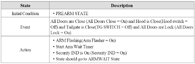
5. PREARM to ARMWAIT
Condition 1
6. REARM to ARMWAIT
Condition 1
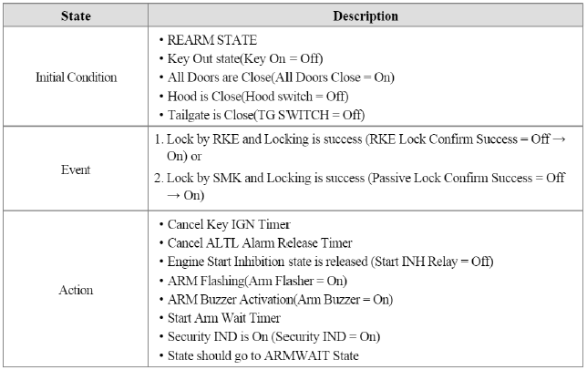
Condition 2
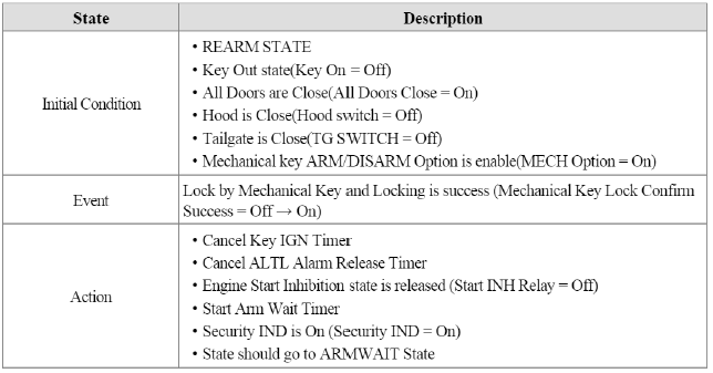
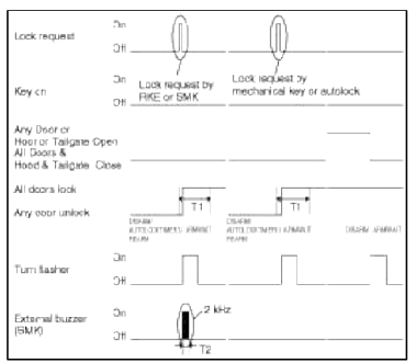
Т1 : Lock fail confirm time, T2 : Arm Disarm buzzer duration
7. ALARM to ARMWAIT
Condition 1
Condition 2
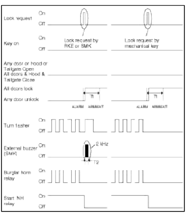
T1 : Lock fail confirm time, T2 : Arm Disarm buzzer duration
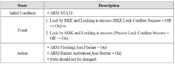
ARM
1. ARMWAIT to ARM
Condition 1
2. ARM to ARM
Condition 1
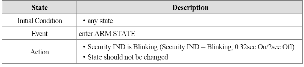
Condition 2
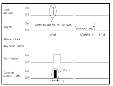
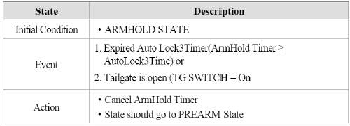
ARMHOLD
1. ARMWAIT to ARMHOLD
Condition 1
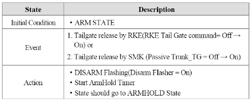
2. ARM to ARMHOLD
Condition 1
3. ARMHOLD to ARMHOLD
Condition 1
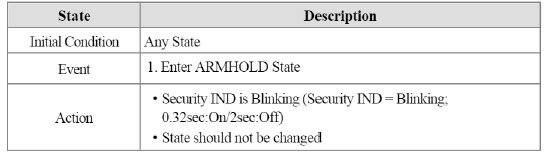
Condition 2
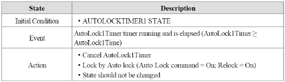
AUTOLOCKTIMER1
1. DISARM to AUTOLOCKTIMER1
Condition 1
2. ARMWAIT to AUTOLOCKTIMER1
Condition 1
T1 : 0.5 +- 0.05 sec
3. ARM to AUTOLOCKTIMER1
Condition 1
4. AUTOLOCKTIMER1 to AUTOLOCKTIMER1
Condition 1
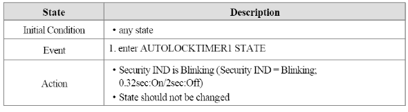
Condition 2
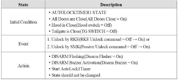
Condition 3
5. ARMHOLD to AUTOLOCKTIMER1
Condition 1
6. REARM to AUTOLOCKTIMER1
Condition 1
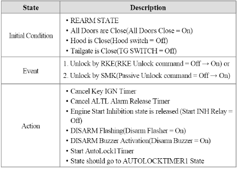
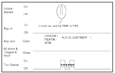
T1 : 0.5 +- 0.05 sec
7. ALARM to AUTOLOCKTIMER1
Condition 1

T1 : 0.5 +- 0.05 sec
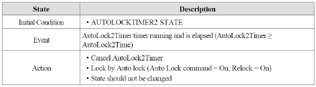
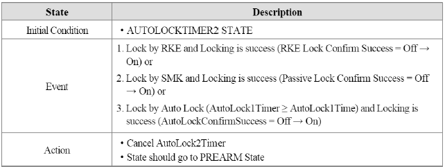
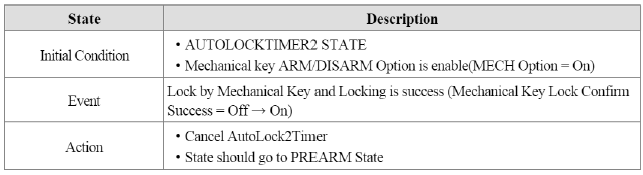
AUTOLOCKTIMER2
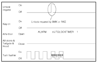
1. DISARM to AUTOLOCKTIMER2
Condition 1

2. AUTOLOCKTIMER2 to AUTOLOCKTIMER2
Condition 1
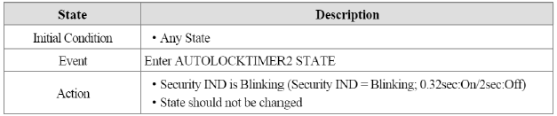
Condition 2
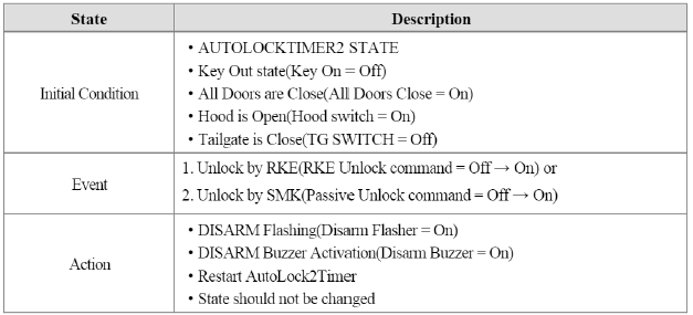
Condition 3
3. PREARM to AUTOLOCKTIMER2
Condition 1
Т1 : 0.5 +- 0.05 sec
4. ALARM to AUTOLOCKTIMER2
Condition 1

T1 : 0.5 +- 0.05 sec
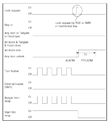
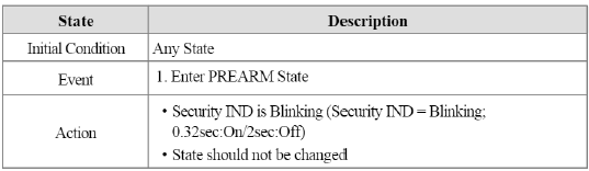
PREARM
1. DISARM to PREARM
Condition 1
Condition 2
Condition 3
Condition 4
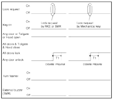
2. AUTOLOCKTIMER2 to PREARM
Condition 1
Condition 2
3. ARMHOLD to PREARM
Condition 1
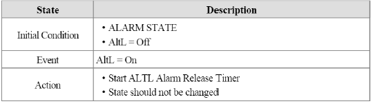
4. ALARM to PREARM
Condition 1
Condition 2
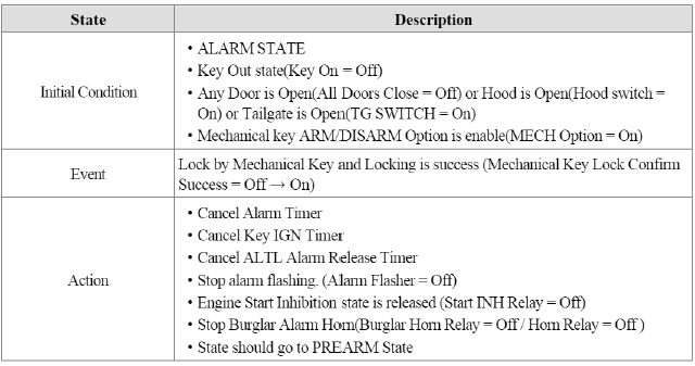
T1 : Lock fail confirm time
5. PREARM to PREARM
Condition 1
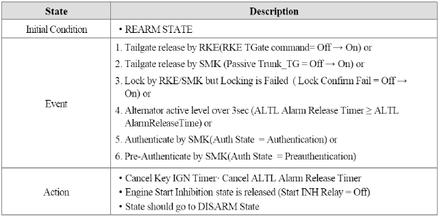
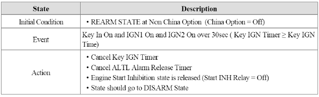
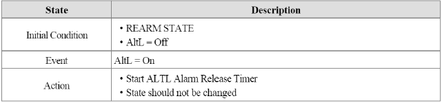
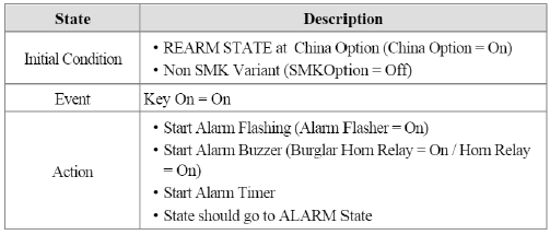
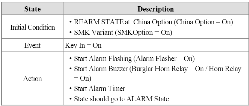
REARM
1. ALARM to REARM
Condition 1
Condition 2
2. REARM to REARM
Condition 1
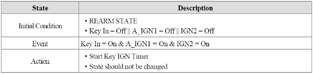
Condition 2
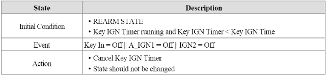
Condition 3
Condition 4
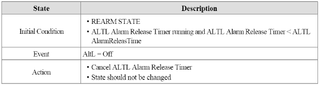
Condition 5
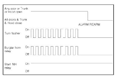
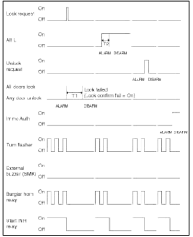
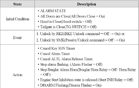
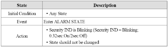
ALARM
- Alarm pattern: MID/China 1 time Alarm flashing and Horn Activation (Alarm On Time 1 time).
- Alarm pattern: GEN 3 times Alarm flashing and Horn Activation (Alarm On Time / Alarm Off Time, 3 time).
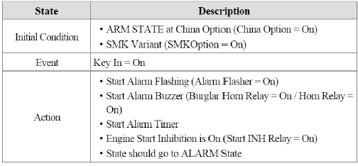
1. ARM to ALARM
Condition 1
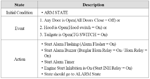
Condition 2
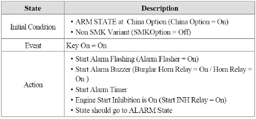
Condition 3
2. REARM to ALARM
Condition 1
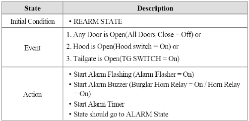
Condition 2
Condition 3
3. ALARM to ALARM
Condition 1
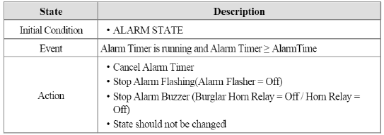
Condition 2

Condition 3

Condition 4
Condition 5
Condition 6
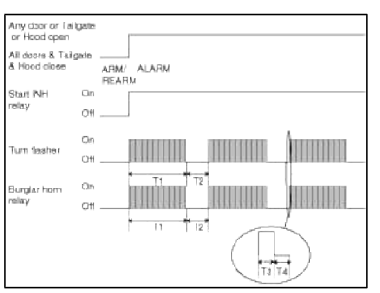
T1 : Alarm single time, T2 : Alarm pause time, T3 : On time, T4 : Off time
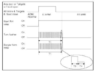
T1 : Alarm single time, T3 : On time, T4 : Off time
READ NEXT:
 Repair procedures
Inspection
Front Door Lock Actuator Inspection
1. Remove the front door trim.
(Refer to the BD group - "Front door")
2. Remove the front door module.
3. Disconnect the 7P conn
Transmitter
Repair procedures
Inspection
1. Check that the red light flickers when the door lock or unlock button is
pressed on the transmitter.
2. Remove the battery (A) and check voltage if the red light
SEE MORE:
Storage compartment
Center console storage
These compartments can be used to
store small items required by the driver
or passengers.
To avoid possible theft, do not leave
valuables in the storage compartment.
Always keep the storage compartment
covers closed while driving. Do
not attempt to place so man
Changing the engine oil and filter
The lubrication, rust prevention, cooling,
and cleaning effect of the engine oil will
gradually degrade during its use. Have
the engine oil and filter changed by an
authorized Kia dealer according to the
Engine Oil Life Management System
instructions or the maintenance schedule.
If the mai
Content
- Home
- Kia Sportage - Fifth generation (NQ5) - (2022-2026) - Owner's Manual
- Kia Sportage - Second generation (JEKM) (2005-2015) - Body Workshop Manual
- Kia Sportage Third generation (SL) - (2011-2016) - Service and Repair Manual
- Sitemap
- Top articles
