Kia Sportage: Repair procedures
Removal
NOTE
Take care not to damage and scratch the hazard lamp switch assembly and its related parts.
Apply the protective tapes to the hazard lamp switch assembly and its related parts.
1. Disconnect the negative (-) battery terminal.
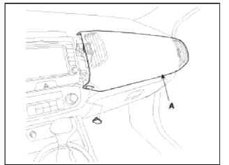
2. Remove the crash pad passenger's garnish (A).
(Refer to BD group - "Crash pad")
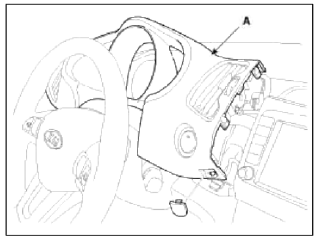
3. Disconnect the connectors and remove the cluster fascia panel (A).
(Refer to BD group - "Crash pad")
4. Remove the center fascia panel (A) after loosening the mounting screw (2EA).
5. Disconnect the connector (A) installed on the center fascia panel.
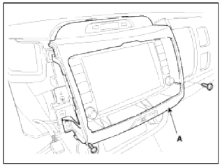
6. Remove the AVN assembly (A) after loosening the mounting screw (4EA).
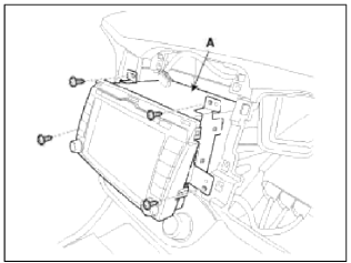
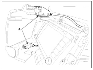
7. Disconnect the AVN connectors (A) and cable, then remove the AVN unit completely.
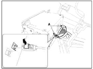
NOTE
Lift the connector locking clip to the arrow direction, disconnect the connector.
When assembling, install the connector and connector locking clip.
CAUTION
- If CD does not eject, don't try to remove it.
- The player may be damaged.
- Therefore, contact a service shop for repairs.
Installation
1. Connect the AVN head unit connectors and cable.
2. Install the AVN head unit.
3. Install the center fascia panel.
4. Install the cluster fascia panel.
5. Install the crash pad passenger's garnish.
6. Connect the negative (-) battery terminal.
NOTE
- Make sure the connector are connected in properly.
- Check the AVN system.
READ NEXT:
 AUX (Auxiliary) Jack
Description and Operation
Description
The multimedia jack on the console tipper cover is for customers who like to
listen to external portable music
players like the MP3, iPod and etc., thr
Specifications, Components and Components Location | Description and Operation
Specifications
Specifications
Smart Key Unit
RF Receiver
Smart Key Fob
Antenna
Components and Components Location
Component Location (1)
Buzzer
Smart key unit
SEE MORE:
Exterior features
Roof rack
If the vehicle has a roof rack, you can
load cargo on top of your vehicle.
Type A
Type B
* The actual shape may differ from the
illustration.
Crossbars and fixing components
needed to install the roof rack on your
vehicle may be obtained from an authorized
Kia dealer or other
Climate control air filter
The climate control air filter installed
behind the glove box filters the dust or
other pollutants that come into the vehicle
from the outside through the heating
and air conditioning system.
Outside air
Recirculated air
Climate control air filter
Blower
Evaporator core
Heater
Content
- Home
- Kia Sportage - Fifth generation (NQ5) - (2022-2026) - Owner's Manual
- Kia Sportage - Second generation (JEKM) (2005-2015) - Body Workshop Manual
- Kia Sportage Third generation (SL) - (2011-2016) - Service and Repair Manual
- Sitemap
- Top articles
