Kia Sportage: Repair procedures
Inspection
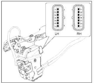
Front Door Lock Actuator Inspection
1. Remove the front door trim.
(Refer to the BD group - "Front door")
2. Remove the front door module.
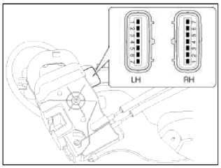
3. Disconnect the 7P connector from the actuator.
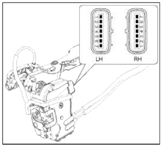
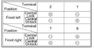
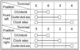
4. Check actuator operation by connecting power and ground according to the table. To prevent damage to the actuator, apply battery voltage only momentarily.
[Central Lock]
Rear Door Lock Actuator Inspection
1. Remove the rear door trim.
(Refer to the BD group - "Rear door")
2. Remove the rear door module.
З. Disconnect the 7P connector from the actuator.
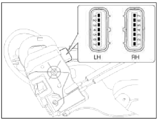
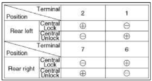
4. Check actuator operation by connecting power and ground according to the table. To prevent damage to the actuator, apply battery voltage only momentarily.
[Central Lock]
Tailgate Release Actuator Inspection
1. Remove the tailgate trim panel.
(Refer to the BD group - "Trunk lid")
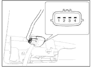
2. Disconnect the 4P connector from the actuator.
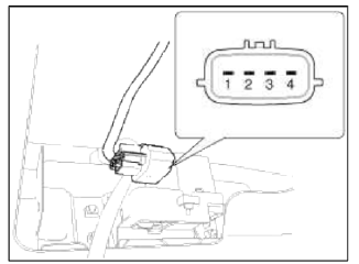
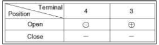
3. Check actuator operation by connecting power and ground according to the table. To prevent damage to the actuator, apply battery voltage only momentarily.
Front Door Lock Switch Inspection
1. Remove the front door trim panel.
(Refer to the BD group - "Front door")
2. Remove the front door module.
З. Disconnect the 7P connector from the actuator.
4. Check for continuity between the terminals in each switch position when inserting the key into the door according to the table.
[Central Lock]
Rear Door Lock Switch Inspection
1. Remove the rear door trim panel.
(Refer to the BD group - "Rear door")
2. Remove the rear door module.
3. Disconnect the 7P connector from the actuator.
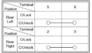
4. Check for continuity between the terminals in each switch position according to the table.
[Central Lock]
Tailgate Lid Open Switch Inspection
1. Remove the tailgate lid trim.
(Refer to the BD group - "Tailgate")
2. Disconnect the 4P connector from the actuator.
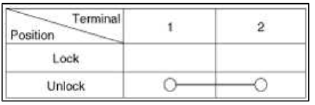
3. Check for continuity between the terminals in each switch position according to the table.
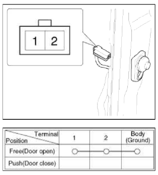
Door Switch Inspection
Remove the door switch and check for continuity between the terminals.
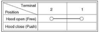
Hood Switch Inspection
1. Disconnect the connector from the hood switch (A).
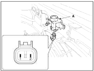
2. Check for continuity between the terminals and ground according to the table.
Burglar Horn Inspection
1. Remove the burglar horn (A) after removing 1 bolt and disconnect the 2P connector from the burglar horn.
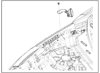
2. Test the burglar horn by connecting battery power to the terminal 1 and ground the terminal 2.
3. The burglar horn should make a sound. If the burglar horn fails to make a sound replace it.
READ NEXT:
 Transmitter
Repair procedures
Inspection
1. Check that the red light flickers when the door lock or unlock button is
pressed on the transmitter.
2. Remove the battery (A) and check voltage if the red light
Specifications, Schematic Diagrams, Description and Operation
Specifications
Specifications
Electrical Performance
Schematic Diagrams
Circuit Diagram
Description and Operation
Description
Body control module receives various input
SEE MORE:
Armed stage
Theft-alarm system
This system is designed to provide protection
from unauthorized entry into the
vehicle.
This system is operated in three stages:
Armed stage
Theft-alarm stage
Disarmed stage
If triggered, the system provides an
audible alarm with blinking of the hazard
warni
Intercooler
Components and
Components Location
Components
Recirculation hose
Intercooler inlet hose & pipe
assembly
Intercooler outlet hose & pipe
assembly
Intercooler mounting bracket
Intercooler upper mounting insulator
Intercooler
Intercooler lower mounting insulator
Content
- Home
- Kia Sportage - Fifth generation (NQ5) - (2022-2026) - Owner's Manual
- Kia Sportage - Second generation (JEKM) (2005-2015) - Body Workshop Manual
- Kia Sportage Third generation (SL) - (2011-2016) - Service and Repair Manual
- Sitemap
- Top articles
