Kia Sportage: Cylinder Head | Removal - Repair procedures - Cylinder Head
Components and Components Location
Components
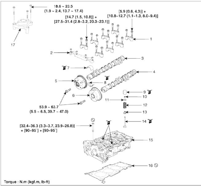
- Camshaft bearing cap
- Camshaft front bearing cap
- Exhaust camshaft
- Intake camshaft
- Exhaust CVVT assembly
- Intake CVVT assembly
- Exhaust camshaft upper bearing
- Exhaust camshaft lower bearing
- MLA
- Retainer lock
- Retainer
- Valve spring
- Valve stem seal
- Valve
- Cylinder head
- Cylinder head gasket
- Fuel pump bracket
Removal - Repair procedures - Cylinder Head
Removal
CAUTION
- Use fender covers to avoid damaging painted surfaces.
- To avoid damaging the cylinder head, wait until the engine coolant temperature drops below normal temperature before removing it.
- When handling a metal gasket, take care not to fold the gasket or damage the contact surface of the gasket.
- To avoid damage, unplug the wiring connectors carefully while holding the connector portion.
NOTE
Mark all wiring and hoses to avoid misconnection.
WARNING
In case of removing the high pressure fuel рumр, high pressure fuel pipe, delivery pipe, and injector, there may be injury caused by leakage of the high pressure fuel. So don't do any repair work right after engine stops.
1. Remove the engine cover.
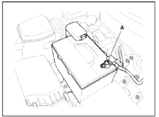
2. Disconnect the battery negative terminal (A).
3. Remove the air cleaner assembly and the intercooler inlet/outlet hoses. (Refer to Engine and transaxle assembly in this group)
4. Remove the RH front wheel.
5. Remove the under cover.
6. Loosen the drain plug, and drain the engine coolant. Remove the radiator cap to drain with speed. (Refer to Cooling system in this group)
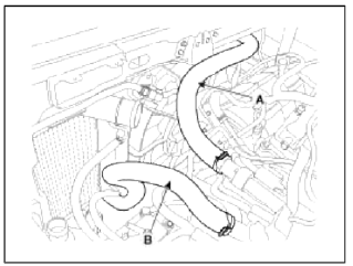
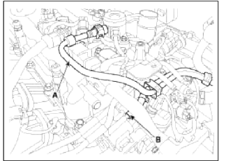
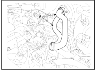
7. Disconnect the radiator upper hose (A) and lower hose (B).
8. Disconnect the wiring connectors and harness clamps, and remove the wiring protectors from the cylinder head, intake manifold and exhaust manifold.
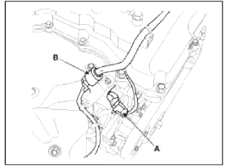
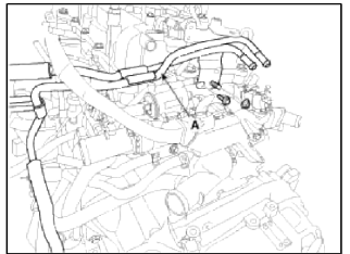
- Disconnect the exhaust OCV (Oil control valve) connector (A) and the oxygen sensor connector (B).
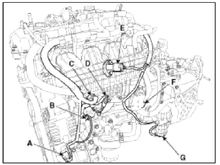
- Disconnect the Ð/С compressor switch connector (A), the alternator connector (B), the OPS (Oil pressure switch) connector & injector extension connector (C), the knock sensor connector (D), the MAPS (Manifold absolute pressure sensor) & IATS (Intake air temperature sensor) connector (E), the ETC (Electronic throttle control) connector (F) and the vacuum pump connector (G).
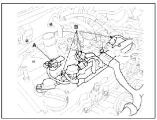
- Disconnect the ignition coil connectors (B) and the fuel pump connector (A).
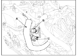
- Disconnect the PCV hose (A), the intake OCV (Oil control valve) connector (B) and the OTS (Oil temperature sensor) connector (C).
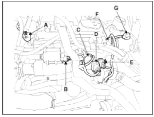
- Disconnect the intake CMPS (Camshaft position sensor) connector (A), the PCSV (Purge control solenoid valve) connector (B), the ECTS (Engine coolant temperature sensor) connector (C), the condenser connector (D), the CKPS (Crankshaft position sensor) connector (E), the exhaust CMPS (Camshaft position sensor) connector (F) and the electric wastegate actuator connector (G).
9. Disconnect the fuel hose (A) and PCSV (Purge control solenoid valve) hose (B).
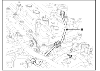
10. Remove the vacuum pipe assembly (A).
11. Remove the high pressure pipe (A). (Refer to FL group)
12. Remove the high pressure fuel pump (A) and the roller tappet (B). (Refer to FL group)
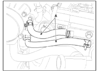
13. Disconnect the heater hoses (A).
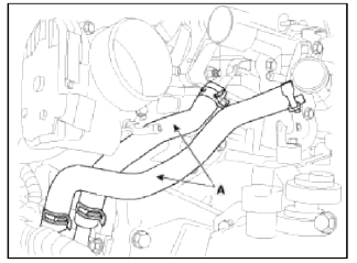
14. Disconnect the throttle body coolant hoses (A).
15. Disconnect the oil cooler coolant hoses (A).
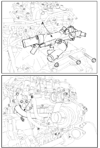
16. Remove the water temperature control assembly (A) with the water inlet pipe (B).
17. Remove the timing chain. (Refer to Timing system in this group)
18. Remove the intake and exhaust manifold. (Refer to Intake and exhaust system in this group)
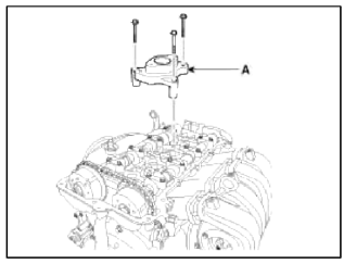
19. Remove the high pressure fuel pump bracket (A).
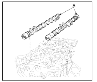
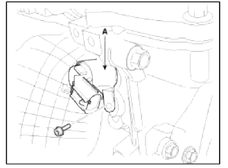
20. Remove the intake CVVT assembly (A) and exhaust CVVT assembly (B).
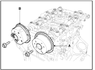
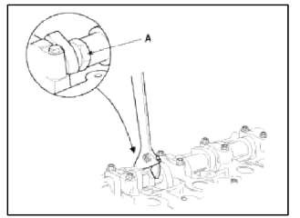
NOTE
When removing the CVVT assembly bolt, prevent the camshaft from rotating by using a wrench at position A.
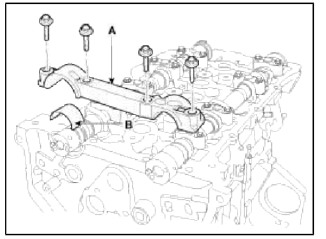
21. Remove the camshaft.
- Remove the front camshaft bearing cap (A) with the upper bearing (B).
- Remove the camshaft bearing cap (A) in the sequence shown.
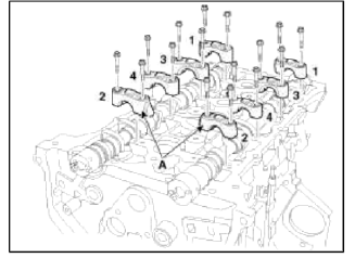
- Remove the camshafts (A).
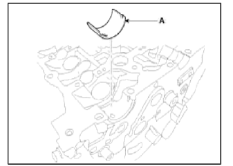
- Remove the exhaust camshaft lower bearing (A).
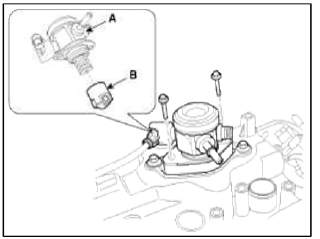
22. Remove the intake OCV (Oil control valve) (A) using a torx wrench and the OTS (Oil temperature sensor) (B).
23. Remove the exhaust OCV (Oil control valve) (A) using a torx wrench.
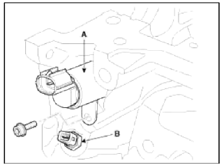
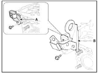
24. Remove the intake CMPS (Camshaft position sensor) (A).
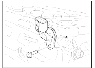
25. Remove the exhaust CMPS (Camshaft position sensor) (A) after removing the engine hanger (B).
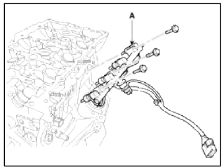
26. Remove the injector & rail module (A). (Refer to FL group)
27. Remove the cylinder head.
- Using triple square wrench, uniformly loosen and remove the 10 cylinder head bolts, in several passes, in the sequence shown. Remove the 10 cylinder head bolts and plate washers.
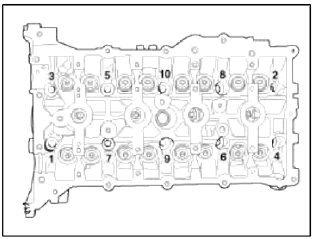
CAUTION
Head warpage or cracking could result from removing bolts in an incorrect order.
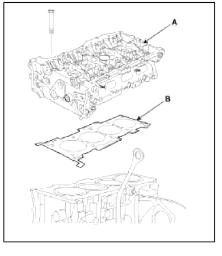
- Lift the cylinder head (A) from the dowels on the cylinder block and place the cylinder head on wooden blocks on a bench.
CAUTION
Be careful not to damage the contact surfaces of the cylinder head and cylinder block.
- Remove the cylinder head gasket (B).
Disassembly
NOTE
Identify MLA (Mechanical Lash Adjuster), valves, valve springs as they are removed so that each item can be reinstalled in its original position.
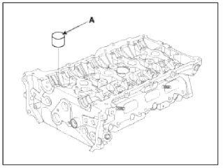
1. Remove the MLAs (A).
2. Remove the valves.
- Using SST (09222-3K000, 09222-3K100), compress the valve spring and remove retainer lock.
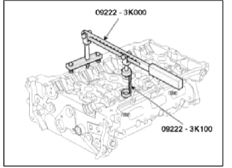
- Remove the spring retainer.
- Remove the valve spring.
- Remove the valve.
- Using needle-nose pliers, remove the valve stem seal.
NOTE
Do not reuse old valve stem seals.
READ NEXT:
 Inspection - Repair procedures - Cylinder Head
Inspection
Cylinder Head
1. Inspect for flatness.
Using a precision straight edge and feeler gauge, measure the surface the
contacting the cylinder block and the
manifolds for warpage.
Flatne
Installation - Repair procedures - Cylinder Head
Installation
NOTE
Thoroughly clean all parts to be assembled.
Always use a new head and manifold gasket.
The cylinder head gasket is a metal gasket. Take care not to bend it.
Rotate the cra
SEE MORE:
Injector
Description and Operation
Description
Based on information from various sensors, the ECM can calculate the fuel
amount to be injected. The fuel injector
is a solenoid-operated valve and the fuel injection amount is controlled by
length of injection time. The ECM
controls each injector
Reassembly - Repair procedures
NOTE
Thoroughly clean all parts to assembled.
Before installing the parts, apply fresh engine oil to all sliding
and rotating surfaces.
Replace all gaskets, O-rings and oil seals with new parts.
1. Assemble the piston and connecting rod.
The piston front mark and the connecting rod
Content
- Home
- Kia Sportage - Fifth generation (NQ5) - (2022-2026) - Owner's Manual
- Kia Sportage - Second generation (JEKM) (2005-2015) - Body Workshop Manual
- Kia Sportage Third generation (SL) - (2011-2016) - Service and Repair Manual
- Sitemap
- Top articles
