Kia Sportage: Troubleshooting
Failure Diagnosis
1. In principle, ESC and TCS controls are prohibited in case of ABS failure.
2. When ESC or TCS fails, only the failed system control is prohibited.
3. The solenoid valve relay should be turned off in case of ESC failure, refer to the ABS fail-safe.
4. Information on ABS fail-safe is identical to the fail-safe in systems where ESC is not installed.
Memory of Fail Code
1. It keeps the code as far as the backup lamp power is connected. (O)
2. It keeps the code as far as the HCU power is on. (X)
Failure Checkup
1. Initial checkup is performed immediately after the HECU power on.
2. Valve relay checkup is performed immediately after the IG2 ON.
3. It executes the checkup all the time while the IG2 power is on.
4. Initial checkup is made in the following cases.
- When the failure is not detected now.
- When ABS and ESC are not in control.
- Initial checkup is not made after ECU power on.
- If the vehicle speed is over 5 mph (8 km/h) when the brake lamp switch is off.
- When the vehicle speed is over 24.8 mph (40 km/h).
5. Though, it keeps on checkup even if the brake lamp switch is on.
6. When performing .ABS or ESC control before the initial checkup, stop the initial checkup and wait for the HECU power input again.
7. Judge failure in the following cases.
- When the power is normal.
- From the point in which the vehicle speed reaches 4.9 mph(8 km/h) after HECU power on.
Countermeasures in Fail
1. Turn the system down and perform the following actions and wait for HECU power OFF.
2. Turn the valve relay off.
3. Stop the control during the operation and do not execute any until the normal condition recovers.
Warning Lamp ON
1. ESC warning lamp turn on for 3sec after IGN ON.
2. ESC function lamp blinks when ESC Act.
3. If ESC fail occured, ESC warning lamp turns ON.
4. ESC OFF lamp turn on in case of
- ESC Switch OFF
- 3sec after IGN ON
Standard Flow of Diagnostic Troubleshooting
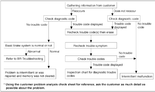
Notes With Regard To Diagnosis
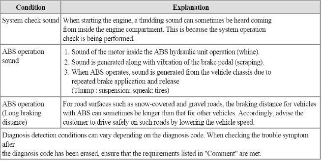
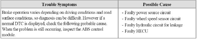
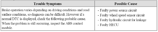
The phenomena listed in the following table are not abnormal.
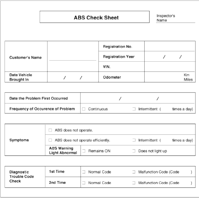
ABS Check Sheet
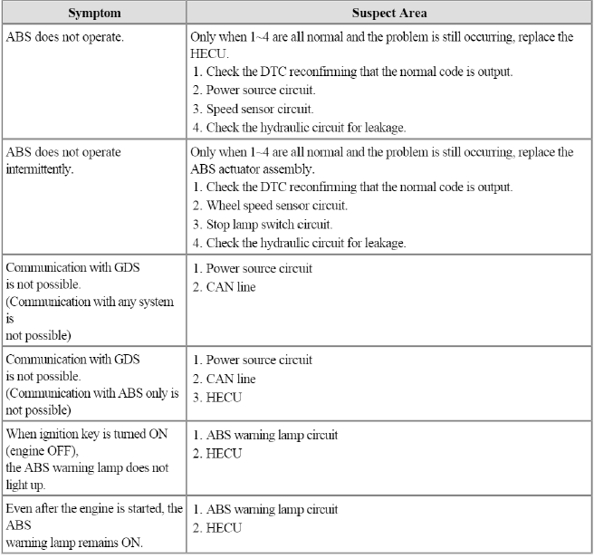
Problem Symptoms Table
CAUTION
During ABS operation, the brake pedal may vibrate or may not be able to be depressed. Such phenomena are due to intermittent changes in hydraulic pressure inside the brake line to prevent the wheels from locking and is not an abnormality.
ABS Does Not Operate.
Detecting condition
Inspection procedures
DTC Inspection
1. Connect the GDS with the data link connector and turn the ignition switch ON.
2. Verify that the normal code is output.
3. Is the normal code output.
 Check the power source circuit.
 Erase the DTC and recheck using GDS.
Check the power source circuit
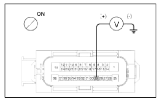
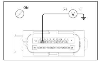
1. Disconnect the connector from the ABS control module.
2. Turn the ignition switch ON, measure the voltage between terminal 29 of the ABS control module harness side connector and body ground.
Specification: approximately B+
3. Is the voltage within specification?
 Check the ground circuit.
Check the harness or connector between the fuse (3Ð) in the engine compartment
junction
block and the ABS control module. Repair if necessary.
Check the ground circuit
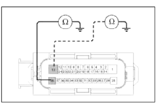
1. Disconnect the connector from the ABS control module.
2. Check for continuity between terminals 13,38 of the ABS control module harness side connector and ground point.
3. Is there continuity?
Check the wheel speed sensor
circuit.
Repair an open in the wire
and ground
point.
Check the wheel speed sensor circuit.
1. Refer to the DTC troubleshooting procedures.
2. Is it normal?
Check the hydraulic circuit
for leakage.
Repair or replace the wheel
speed
sensor.
Check the hydraulic circuit for leakage
1. Refer to the hydraulic lines.
2. Inspect leakage of the hydraulic lines.
3. Is it normal?
The problem is still
occulting, replace the ABS control
module.
Repair the hydraulic lines
for leakage.
ABS Does Not Operate (Intermittently).
Detecting condition
Inspection procedures
DTC Inspection
1. Connect the GDS with the data link connector and turn the ignition switch ON.
2. Verify that the normal code is output.
3. Is the normal code output?
Check the wheel speed sensor
circuit.
Erase the DTC and recheck
using GDS.
Check the wheel speed sensor circuit
1. Refer to the DTC troubleshooting procedures.
2. Is it normal?
Check the stop lamp switch
circuit.
Repair or replace the wheel
speed
sensor.
Check the stop lamp switch circuit
1. Check that stop lamp lights up when brake pedal is depressed and turns off when brake pedal is released.
2. Measure the voltage between terminal 23 of the ABS control module harness side connector and body ground when brake pedal is depressed.
Specification: approximately B +
3. Is the voltage within specification?
Check the hydraulic circuit
for leakage.
Repair the stop lamp switch.
Repair an open in the wire between the ABS control module
and the stop lamp switch.
Check the hydraulic circuit for leakage
1. Refer to the hydraulic lines.
2. Inspection leakage of the hydraulic lines.
3. Is it normal?
The problem is still
occurring, replace the ABS control
module.
Repair the hydraulic lines
for leakage.
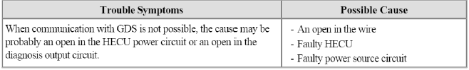
Communication with GDS is not possible.
(Communication with any system is not possible)
Detecting condition
Inspection procedures
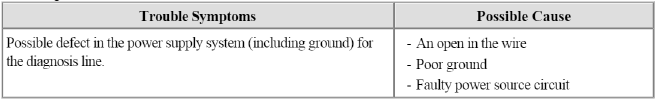
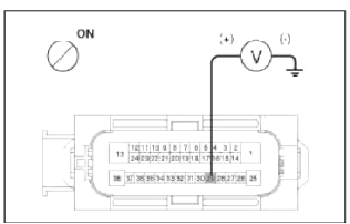
Check The Power Supply Circuit For The Diagnosis
1. Measure the voltage between terminal 9 of the data link connector and body ground.
Specification: approximately B +
2. Is voltage within specification?
Check the ground circuit for
the diagnosis.
Repair an open in the wire.
Check and replace fuse (15A) from the engine compartment
junction block.
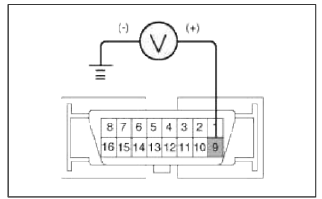
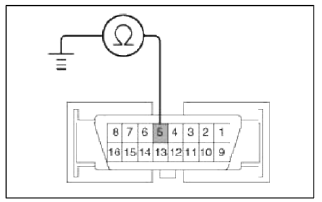
Check the ground circuit for the diagnosis
1. Check for continuity between terminal 5 of the data link connector and body ground.
2. Is there continuity?
Repair an open in the wire
between terminal 5 of the data link connector and
ground point.
Communication with GDS is not possible.
(Communication with ABS only is not possible)
Detecting condition
Inspection procedures
Check for Continuity in the CAN Line
1. Disconnect the connector from the ABS control module.
2. Check for continuity between terminals 26,14 of the ABS control module connector and 3,11 of the data link connector.
3. Is there continuity?
Check the power source of
.ABS control
module.
Repair an open in the wire.
Check the power source of ABS control module
1. Disconnect the connector from the ABS control module.
2. Turn the ignition switch ON, measure the voltage between terminal 29 of the ABS control module harness side connector and body ground.
Specification: approximately B +
3. Is voltage within specification?
Check for poor ground.
Check the harness or
connector between the fuse (7.5A) in the engine compartment junction
block and the ABS control module. Repair if necessary.
Check for poor ground
1. Check for continuity between terminal 5 of the data link connector and ground point.
Replace the ABS control
module and recheck.
Repair an open in the wire or
poor ground.
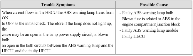
When Ignition Key Is Turned ON (engine OFF), The ABS Warning Lamp Does Not Light Up.
Detecting condition
Inspection procedures
Problem verification
1. Disconnect the connector from the ABS control module and turn the ignition switch ON.
2. Does the ABS warning lamp light up?
Inspect again after replacing
the ABS HECU.
Check the power source for
the ABS warning
lamp.
Check the power source for the ABS warning lamp
1. Disconnect the instrument cluster connector (M15) and turn the ignition switch ON.
2. Measure the voltage between terminal (M15) 39 of the cluster harness side connector and body ground.
Specification: approximately B +
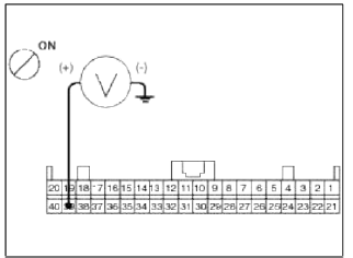
3. Is voltage within specification?
Check the CAN circuit
resistance for ABS warning
lamp.
Check for blown fuse.
Check the CAN circuit resistance for ABS warning lamp
1. Turn the ignition switch OFF. Disconnect the instrument cluster connector (M15).
2. Measure the resistance between terminal (M15) 36 and 37 of the cluster harness side connector.
Specification : 60Ω
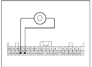
3. Is resistance within specification?
Repair ABS warning lamp bulb
or instrument cluster assembly.
Check the CAN circuit wiring
for ABS warning lamp.
Check the CAN circuit wiring for ABS warning lamp
1. Turn the ignition switch OFF. Disconnect the instrument cluster connector (M15) and ABS HECU connector.
2. Check for continuity between terminal (Ml5) 36 of the cluster harness side connector and terminal 26 of ABS HECU harness side.
Check for continuity between terminal (Ml5) 37 of the cluster harness side connector and terminal 14 of ABS HECU harness side.
Specification : Below 1Ω
3. Is resistance within specification?
Repair short circuit wiring
between terminal 26,14 of ABS HECU harness connector and ABS
warning lamp module.
Repair open circuit wiring
between terminal 26,14 of ABS HECU harness connector and ABS
warning lamp module.
Even After The Engine Is Started, The ABS Warning Lamp Remains ON.
Detecting condition
Inspection procedures
Check DTC Output
1. Connect the GDS to the 16P data link connector located behind the driver's side kick panel.
2. Check the DTC output using GDS.
3. Is DTC output?
Perform the DTC
troubleshooting procedure (Refer to DTC
troubleshooting).
Check the CAN circuit
resistance for ABS warning lamp.
Check the CAN circuit resistance for ABS warning lamp
1. Turn the ignition OFF. Disconnect the instrument cluster connector (M15).
2. Measure the resistance between terminal (M15) 36 and 37 of the cluster harness side connector.
Specification : 60Ω
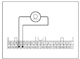
3. Is resistance within specification?
Repair ABS warning lamp bulb
or instrument cluster
assembly.
Check the CAN circuit wiring
for ABS warning lamp.
Check the CAN circuit wiring for ABS warning lamp
1. Turn the ignition switch OFF. Disconnect the instrument cluster connector (M15) and ABS HECU connector.
2. Check for continuity between terminal (Ml5) 36 of the cluster harness side connector and terminal 26 of ABS HECU harness side.
Check for continuity between terminal (Ml5) 37 of the cluster harness side connector and terminal 14 of ABS HECU harness side.
Specification : Below 1Ω
3. Is there continuity?
Repair short circuit wiring
between terminal 26,14 of ABS HECU harness connector and
ABS warning lamp module. If no trouble in wiring, inspect again after replacing
the ABS
HECU.
Repair short circuit wiring
between terminal 26,14 of ABS HECU harness connector and
ABS warning lamp module. If no trouble in wiring, inspect again after replacing
the ABS
HECU.
Bleeding of Brake System
This procedure should be followed to ensure adequate bleeding of air and filling of the ESC unit, brake lines and master cylinder with brake fluid.
1. Remove the reservoir cap and fill the brake reservoir with brake fluid.
CAUTION
If there is any brake fluid on any painted surface, wash it off immediately.
NOTE
When pressure bleeding, do not depress the brake pedal.
Recommended fluid.......DOT3 or DOT4
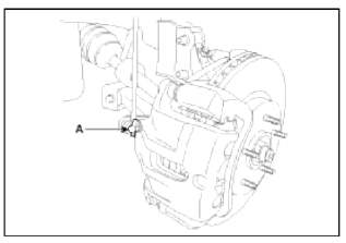
2. Connect a clear plastic tube to the wheel cylinder bleeder plug and insert the other end of the tube into a half filled clear plastic bottle.
3. Connect the GDS to the data link connector located underneath the dash panel.
4. Select and operate according to the instructions on the GDS screen.
- Select vehicle name.
- Select Anti-Lock Brake system.
- Select HCU air bleeding mode.
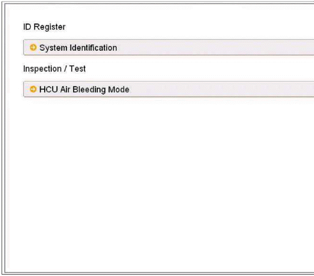
- Press "OK" to operate motor pump and solenoid valve.
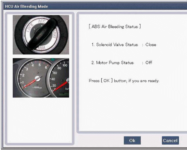
- Wait 60 sec. before operating the air bleeding.
(If not, yon may damage the motor.)
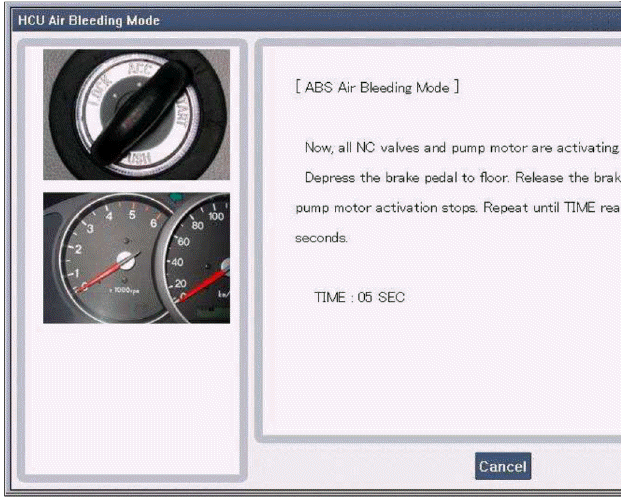
- Perform the air bleeding.
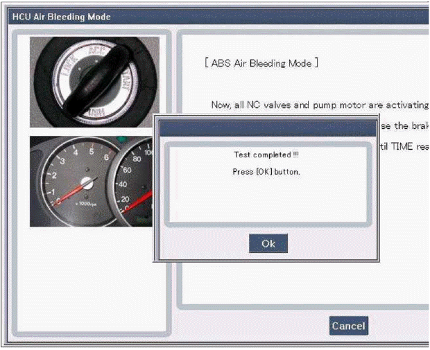
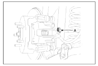
5. Pump the brake pedal several times, and then loosen the bleeder screw until fluid starts to run out without bubbles. Then close the bleeder screw (A).
Front
Rear
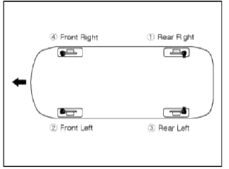
6. Repeat step 5 until there are no more bubbles in the fluid for each wheel using the chart below for the order of bleeding process.
7. Tighter the bleeder screw.
Bleed screw tightening torque: 7 ~ 13 N.m (0.7 ~ 1.3 kgf.m, 5.4 ~ 9.5 lb-ft)
READ NEXT:
 EBD (Electronic Brake-force Distribution) | ESC Control Module
Description and Operation
Operation
The EBD system (Electronic Brake force Distribution) as a sub-system of the ABS system is to control the maximum braking effectiveness by the rear wheels.
Front Wheel Speed Sensor | Rear Wheel Speed Sensor
Components and Components Location
Components
Front wheel speed sensor connector
Front wheel speed sensor
Repair procedures
Removal
1. Remove the front wheel speed sensor mou
SEE MORE:
Components and Components Location | Steering Column and Shaft
Components
Steering wheel
Steering column
ECU
Motor
Steering gear box
MDPS Circuit Diagram
Harness Connector
Battery
Battery -
Battery +
Vehicle
IGN
-
-
Components and Components Location | Description and Operation
Components
Hands free call switch
Mic
Front left speaker
Front right speaker
Audio head unit (hands free control)
There is no hands free jack. This system supports Ð’luetooth (wireless system).
Description and Operation
Function
Bluetooth Audio
Content
- Home
- Kia Sportage - Fifth generation (NQ5) - (2022-2026) - Owner's Manual
- Kia Sportage - Second generation (JEKM) (2005-2015) - Body Workshop Manual
- Kia Sportage Third generation (SL) - (2011-2016) - Service and Repair Manual
- Sitemap
- Top articles
