Kia Sportage: Valve Body
Description and Operation
Description
The valve body is essential to automatic transaxle control and consists of various valves used to control the oil feed from the oil pump. Specifically, these valves consist of pressure regulator valves, oil redirection valves, shift valves, and manual valves. The body also features electronic solenoid valves that ensure smooth gear changes.
Components and Components Location
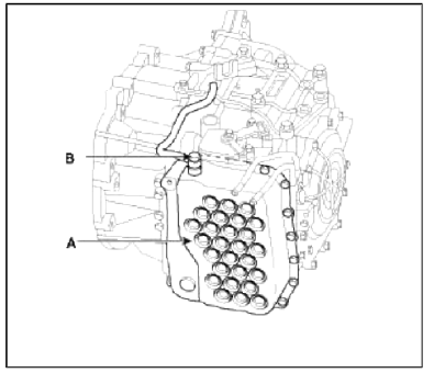
Components Location
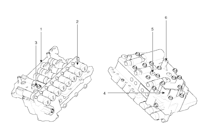
- PCV adjust screw
- Solenoid valve
- Oil temperature sensor
- Accumulator
- Low & reverse brake (LR/B) pressure flow hole
- Under drive brake (UD/B) pressure flow hole
Valve Body Flow
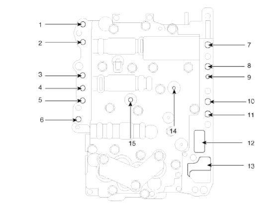
- To cooler
- From cooler
- Lubrication (rear)
- Overdrive pressure
- Reducing pressure (red2)
- Reducing pressure (red1)
- From damper pressure
- To damper pressure
- Lubrication (front)
- 35R clutch pressure
- 26 brake pressure
- From oil pump
- To oil pump
- Underdrive pressure
- Low & reverse pressure
Repair procedures
Removal
1. Remove the battery and the battery trау. (Refer to "Charging system" in EE group.)
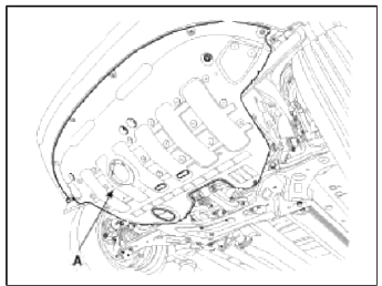
2. Remove the under cover (A).
Tightening torque: 19.6 ~ 24.5 N.m (2.0 ~ 2.5 kgf.m, 14.5 ~ 18.1 lb-ft)
3. Replace new gasket and the plug after draining the automatic transaxle fluid by removing the drain plug. (Refer to "Hydraulic system (Fluid)" in this group)
4. Remove the valve body cover (A) and eyebolt (B).
Tightening torque:
(A) 13.8 ~ 14.7 N.m (1.3 ~ 1.5 kgf.m, 9.4 ~ 10.8 lb-ft)
(B) 34.3 ~ 44.1 N.m (3.5 ~ 4.5 kgf.m, 25.3 ~ 32.6 lb-ft)
CAUTION
Always replace the gasket of the eyebolt use new one whenever loosening eyebolt.
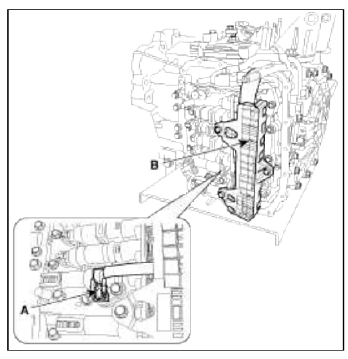
5. Remove the plate and the detent spring (A) after removing the bolt.
Tightening torque: 24.5 ~ 35.3 N.m (2.5 ~ 3.6 kgf.m, 18.1 ~ 26.0 lb-ft)
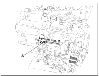
6. Remove the bolt (3ea) after disconnecting the solenoid valve (B) connector and the oil temperature sensor connector (A).
Tightening torque: 9.8 ~ 11.8 N.m (1.0 ~ 1.2 kgf.m, 7.2 ~ 8.7 lb-ft)
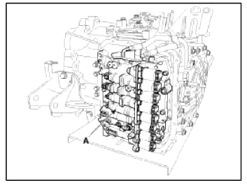
7. Remove the valve body assembly (A).
Tightening torque: 9.8 ~ 11.8 N.m (1.0 ~ 1.2 kgf.m, 7.2 ~ 8.7 lb-ft)
Installation
1. Installation is the reverse of removal.
CAUTION
After replacement or reinstallation procedure of the valve body assembly, must perform procedures below.
NOTE
- Continue to apply liquid gasket at application points at the valve body cover with Ø2.5mm (0.0984in.) thickness.
Liquid gasket Part name : Threebond 1281B or LOCTITE FMD-546
- Adding automatic transaxle fluid. (Refer to "Hydraulic system (Fluid)" in this group)
- Perform TCM learning after replacing the valve body to prevent slow transaxle response, jerky acceleration and jerky startup. (Refer to "Automatic transaxle control system (Repair procedures)" in this group)
READ NEXT:
 Description and Operation, Components and Components Location | Flow Diagram
Description and Operation
Description
The 6-spd automatic transaxle consists of an overdrive clutch (OD/C), a one-way clutch (OWC), a lower and reverse brake (LR/B), an underdrive brake (UD/B
SEE MORE:
Cylinder Head | Removal - Repair procedures - Cylinder Head
Components and Components Location
Components
Camshaft bearing cap
Camshaft front bearing cap
Exhaust camshaft
Intake camshaft
Exhaust CVVT assembly
Intake CVVT assembly
Exhaust camshaft upper bearing
Exhaust camshaft lower bearing
MLA
Ret
Precautions For Catalytic Converter
CAUTION
If a large amount of unburned gasoline flows into the converter, it may
overheat and create a fire hazard. To
prevent this observe the following precautions and explain them to your
customer.
1. Use only unleaded gasoline.
2. Do not run the engine while the car is at rest for a lon
Content
- Home
- Kia Sportage - Fifth generation (NQ5) - (2022-2026) - Owner's Manual
- Kia Sportage - Second generation (JEKM) (2005-2015) - Body Workshop Manual
- Kia Sportage Third generation (SL) - (2011-2016) - Service and Repair Manual
- Sitemap
- Top articles
