Kia Sportage: Accelerator Position Sensor (APS) | Fuel Tank Pressure Sensor (FTPS)
Description and Operation
Description
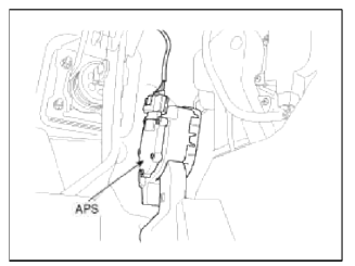
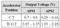
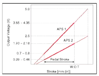
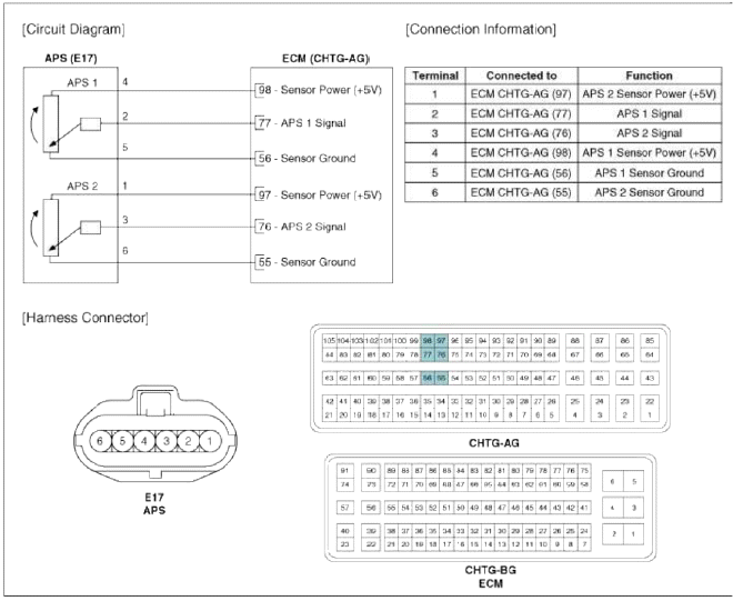
Accelerator Position Sensor (APS) is installed on the accelerator pedal module and detects the rotation angle of the accelerator pedal. The APS is one of the most important sensors in engine control system, so it consists of the two sensors which adapt individual sensor power and ground line. The second sensor monitors the first sensor and its output voltage is half of the first one. If the ratio of the sensor 1 and 2 is out of the range (approximately 1/2), the diagnostic system judges that it is abnormal.
Specifications
Specification
Schematic Diagrams
Circuit Diagram
Repair procedures
Inspection
1. Connect the GDS on the Data Link Connector (DLC).
2. Turn the ignition switch ON.
3. Measure the output voltage of the APS 1 and 2 at C.T and W.O.T
Specification: Refer to "Specification"
Removal
Refer to "Accelerator Pedal" in this group.
Installation
Refer to "Accelerator Pedal" in this group.
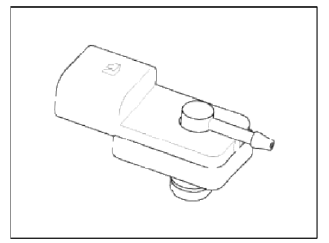
Fuel Tank Pressure Sensor (FTPS)
Description and Operation
Description
Fuel Tank Pressure Sensor (FTPS) is a component of the evaporative emission control system. It is installed on the fuel tank near the fuel pump assembly. It checks the evaporative system and detects an evaporative leak in the system.
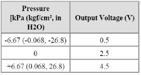
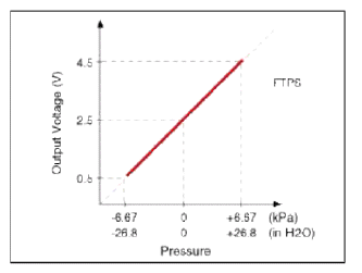
Specifications
Specification
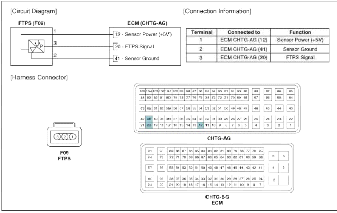
Schematic Diagrams
Circuit Diagram
Repair procedures
Inspection
1. Connect the GDS on the Data Link Connector (DLC).
2. Measure the output voltage of the FTPS.
Specification: Refer to "Specification"
Removal
1. Turn the ignition switch OFF and disconnect the battery negative (-) cable.
2. Remove the rear seat (Refer to "Seat" in BD group).
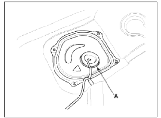
3. Remove the fuel pump service cover (A).
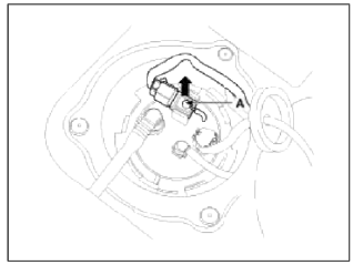
4. Disconnect the fuel tank pressure sensor connector (A).
5. Remove the fuel tank pressure sensor after releasing the hooks vertically.
Installation
CAUTION
- Install the component with the specified torques.
- Note that internal damage may occur when the component is dropped. If the component has been dropped, inspect before installing.
CAUTION
- Insert the sensor in the installation hole and be careful not to damage.
1. Installation is reverse of removal.
READ NEXT:
 Injector
Description and Operation
Description
Based on information from various sensors, the ECM can calculate the fuel
amount to be injected. The fuel injector
is a solenoid-operated valve and the
Purge Control Solenoid Valve (PCSV)
Description and
Operation
Description
Purge Control Solenoid Valve (PCSV) is installed on the surge tank and
controls the passage between the canister
and the intake manifold. It is a sole
SEE MORE:
Blower Unit | Blower Motor
Components and Components Location
Component Location
Components
Intake case (LH)
Intake case (RH)
Blower motor
Intake door
Intake actuator
Mofet [Auto type]
Resistor [Manual type]
Climate control air filter cover
Climate control air f
Troubleshooting
Basic Troubleshooting
Basic Troubleshooting Guide
Customer Problem Analysis Sheet
Basic Inspection Procedure
Measuring Condition of Electronic Pails' Resistance
The measured resistance at high temperature after vehicle running may be high
or low. So all resistance must be
measu
Content
- Home
- Kia Sportage - Fifth generation (NQ5) - (2022-2026) - Owner's Manual
- Kia Sportage - Second generation (JEKM) (2005-2015) - Body Workshop Manual
- Kia Sportage Third generation (SL) - (2011-2016) - Service and Repair Manual
- Sitemap
- Top articles
