Kia Sportage: Injector
Description and Operation
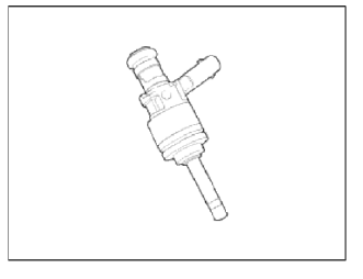
Description
Based on information from various sensors, the ECM can calculate the fuel amount to be injected. The fuel injector is a solenoid-operated valve and the fuel injection amount is controlled by length of injection time. The ECM controls each injector by grounding the control circuit. When the ECM energizes the injector by grounding the control circuit, the circuit voltage should be low (theoretically 0V) and the fuel is injected. When the ECM deenergizes the injector by opening control circuit, the fuel injector is closed and circuit voltage should momentarily peak, and then settle at system voltage.
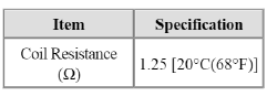
Specifications
Specification
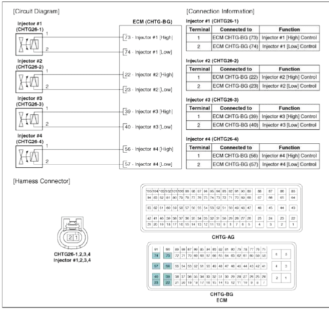
Schematic Diagrams
Circuit Diagram
Repair procedures
Inspection
1. Turn the ignition switch OFF.
2. Disconnect the injector connector.
3. Measure resistance between the injector terminals 1 and 2.
4. Check that the resistance is within the specification.
Specification: Refer to "Specification"
Removal
WARNING
In case of removing the high pressure fuel pump, high pressure fuel pipe, delivery pipe, and injector, there may be injury caused by leakage of the high pressure fuel. So don't do any repair work right after engine stops.
1. Turn the ignition switch OFF and disconnect the battery negative (-) cable.
2. Release the residual pressure in fuel line (Refer to "Release Residual Pressure in Fuel Line" in this group).
CAUTION
When removing the fuel pump relay, a Diagnostic Trouble Code (DTC) may occur. Delete the code with the GDS after completion of "Release Residual Pressure in Fuel Line" work.
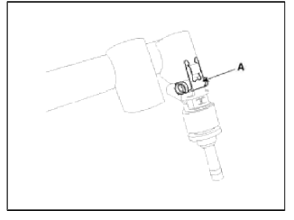
3. Remove the delivery pipe & injector assembly (Refer to "Delivery Pipe" in this group).
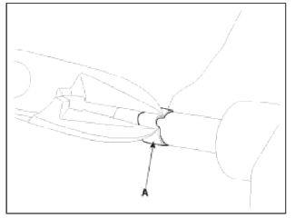
4. Remove the retaining clip (A), and then separate the injector from the delivery pipe.
Installation
CAUTION
Do not reuse the injector retaining clip. O-ring, backup ring, washer seal or combustion sealring. Once an injector is removed, the five components must be replaced with new ones.
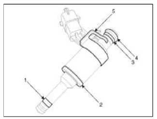
- Combustion seal
- Washer seal
- Backup ring
- O-ring
- Retaining clip
NOTE
- Item 1,3 and 4 are supplied in a single kit.
CAUTION
- Install the component with the specified torques.
- Note that internal damage may occur when the component is dropped. If the component has been dropped, inspect before installing.
CAUTION
- Apply engine oil to the injector O-ring.
CAUTION
- Do not reuse the delivery pipe mounting bolts. Once the delivery pipe is removed, the bolts must be replaced with new ones.
CAUTION
- When inserting the injector, be careful not to damage the injector tip.
CAUTION
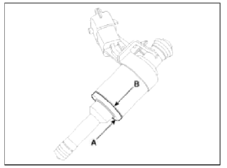
- When replacing the washer seal, the steal plate (A) part should be faced the cylinder installation part and the rubber plate (B) part should be faced the injector body part.
CAUTION
- Do not reuse the combustion seal.
- Be careful not to apply engine oil on the combustion seal ring.
CAUTION
- Avoid dropping the fuel pipe (including injectors) or bumping it into any hard objects since damage to the internal components may occur. If necessary, visually inspect and confirm proper operation with performance tests prior to reuse.
- Before installing the injector into the cylinder head, clean the injector hole and avoid contaminants from entering inside the injector hole. When installing the injector, avoid bumping the injector tip into any of the surrounding components since the tip may become damaged from the impact.
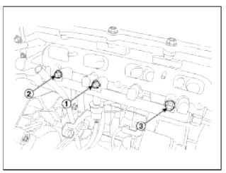
- When fastening the thrее fuel delivery pipe mounting bolts, fully hand-tighten first, and then tighten in the proper sequence ( (1) → (2) → (3) ) in several cycles up to the specified torque. The delivery pipe should move less than 1/8 inch (approx. 3mm), whenever each bolt is tightened.
1. Installation is reverse of removal.
Replacement
The injector combustion seal should be replaced new one to prevent leakage after removing the injector.
1. Remove the combustion seal (A) with a wire cutter.
CAUTION
Grip the sealing ring carefully, pull it to form a small loop and then cut it.
Be careful not to damage the surface of the valve sleeve with the wire cutter.
2. Before the assembly of the sealing ring the groove must be cleaned using a clean cloth.
Any coking of the injector sealing surface must be carefully removed with a brass-wire brush.
CAUTION
The surfaces of the new sealing ring must be clean and free of grease.
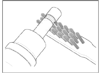
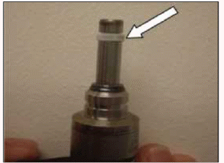
3. Place the combustion seal on the cone and pull downward on the seal as indicated in the photo.
NOTE
Your fingers will work better for installing the Combustion Seal over the cone.
4. Pull the seal downward until it is near the bottom of the cone as shown in the photo.
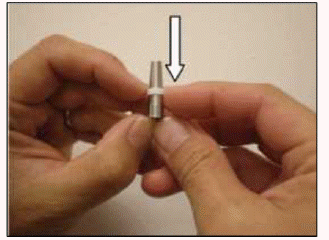
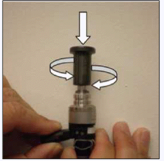
5. Place the cone (with seal) on the end of the injector.
Place the sizing tool (SST No.: 09353-2B000) over the cone. Make sure the tool flange is toward the seal as shown.
Press down on the tool to work the seal over the injector and into the groove.
6. Because the seal will stretch as it goes over the end of the injector, it will be a bit oversized after installation.
By letting the injector and seal set for a few minutes, the seal may reduce in size.
Inspect the seal for damage before continuing.
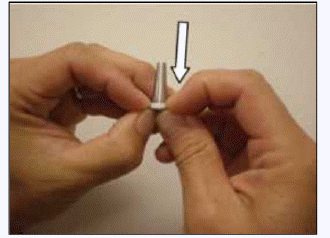
7. Place the resizing tool (flange up) over the seal. Twist the tool slightly while pushing down over the seal. This should reduce the size of the seal.
CAUTION
Be careful not to apply engine oil on the combustion seal ring.
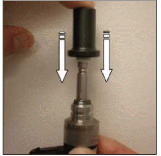
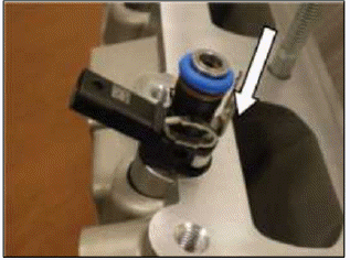
8. Place injector into the head as shown.
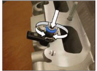
9. Twist slightly while pressing the injector into position in the head.
This should complete the resizing of the seal.
Remove the injector and inspect the seal before completing the injector installation process.
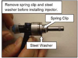
10. If the injector comes with a protective steel washer held in place by a spring clip; both will have to be removed before installation.
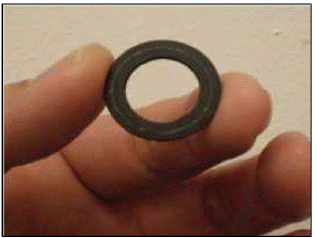
11. Install the Washer Seal onto injector with the rubber side (stepped) toward the injector.
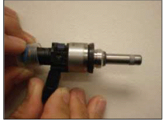
12. The stepped rubber side of the seal goes towards the injector.
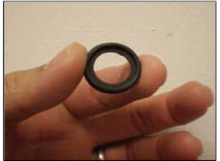
13. The flat washer side of the seal goes towards the head.
READ NEXT:
 Purge Control Solenoid Valve (PCSV)
Description and
Operation
Description
Purge Control Solenoid Valve (PCSV) is installed on the surge tank and
controls the passage between the canister
and the intake manifold. It is a sole
CVVT Oil Control Valve (OCV)
Description and Operation
Description
Continuous Variable Valve Timing (CWT) system advances or retards the valve
timing of the intake and exhaust
valve in accordance with the ECM control s
Fuel Pressure Control Valve | Electric WGT Control Actuator
Description and Operation
Description
Fuel Pressure Regulator Valve is installed on the high pressure fuel pump and controls fuel flow flowing into the injectors in accordance with the ECM si
SEE MORE:
Manual Speed Limit Assist (MSLA)
Speed Limit indicator
Set speed
You can set the speed limit when you do
not want to drive over a specific speed.
If you drive over the preset speed limit,
the warning function operates (set
speed limit will blink, and chime will
sound) until the vehicle speed returns
within the s
Purge Control Solenoid Valve (PCSV)
Description and
Operation
Description
Purge Control Solenoid Valve (PCSV) is installed on the surge tank and
controls the passage between the canister
and the intake manifold. It is a solenoid valve and is open when the ECM grounds
the valve control line. When the
passage is open (PCS
Content
- Home
- Kia Sportage - Fifth generation (NQ5) - (2022-2026) - Owner's Manual
- Kia Sportage - Second generation (JEKM) (2005-2015) - Body Workshop Manual
- Kia Sportage Third generation (SL) - (2011-2016) - Service and Repair Manual
- Sitemap
- Top articles
