Kia Sportage: Components and Components Location, Description and Operation
Kia Sportage Third generation (SL) - (2011-2016) - Service and Repair Manual / Suspension System / Tire Pressure Monitoring System / Components and Components Location, Description and Operation
Components and Components Location
Components Location
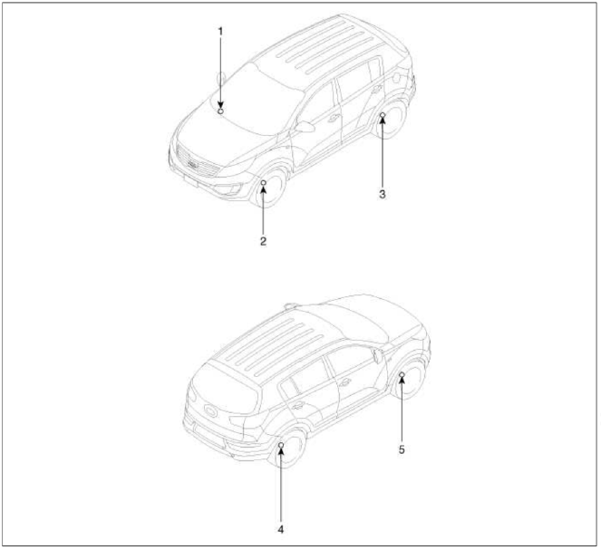
- Receiver
- TPMS Sensor
- TPMS Sensor
- TPMS Sensor
- TPMS Sensor
Description and Operation
Description
TREAD Lamp
- Tire Under Inflation / Leak Warning.

1. Turn on condition
- When tire pressure is below allowed threshold
- When rapid leak is detected by the sensor.
- Indicates that the needs to be re-inflated to placard pressure / repaired.
2. Turn off condition
- Under-inflation; When tire pressure is above (warning threshold + hysteresis).
- Rapid Leak; When the pressure is above (leak warning threshold).
DTC Warning
1. Turn on condition
- When the system detects a fault that is external to the receiver/ sensor.
- When the system detects a receiver fault.
- When the system detects a sensor fault.
2. Turn off condition
- If the fault is considered as 'critical', then the lamp is held on throughout the current Ignition cycle (even if the DTC has been de-activated). This is because it is important to bring the problem to the drivers attention. On the following Ignition cycle, the de-activated conditions will be re-checked. If the de-activate conditions occur, the lamp will be turned off. It will be held on until DTC demotion checking is completed.
- 'Non critical' faults are those that can occur temporarily e.g. vehicle battery under voltage. The lamp is therefore turned off when the DTC demotion condition occurs.
System Fault
1. General Function
- The system monitors a number of inputs across time in order to determine that a fault exists.
- Faults are prioritized according to which has the most likely cause.
- Maximum fault stored is equal to 15.
- Certain faults are not covered through DTC. The main ones are:
- Sensor thermal shutdown (over 257ºF/125ºC).
- Ignition Line stuck; requires observation of lamps at Ignition ON to diagnose.
READ NEXT:
 TPMS Sensor
Description and Operation
Description
1. Mode
Configuration State
All sensors should be in the Low Line (Base) state.
In Low Line (Base) configuration, sensor transmissions occur e
TPMS Receiver
Components and
Components Location
Components
TPMS Receiver Circuit Diagram
Harness Connector
Battery
CAN_High
GND
-
-
-
IGN
CAN_Low
-
-
-
-
Description and
SEE MORE:
Instrument panel overview/Engine compartment
Instrument panel overview
Audio remote control button
Driver's front air bag
Horn
Driving Assist button
Instrument cluster
Light control/turn signals lever
Wiper and washer control lever
Infotainment system
Hazard warning flasher switch
Climate control system/
Daytime Running Light (DRL)
The Daytime Running Light (DRL) can
make it easier for others to see the front
of your vehicle during the day.
The DRL can be helpful in many different
driving conditions, and it is especially
helpful after dawn and before sunset.
The DRL will turn the dedicated lamp
OFF when:
The hea
Content
- Home
- Kia Sportage - Fifth generation (NQ5) - (2022-2026) - Owner's Manual
- Kia Sportage - Second generation (JEKM) (2005-2015) - Body Workshop Manual
- Kia Sportage Third generation (SL) - (2011-2016) - Service and Repair Manual
- Sitemap
- Top articles
