Kia Sportage: Alignment
Repair procedures
Front Wheel Alignment
CAUTION
When using a commercially available computerized wheel alignment equipment to inspect the front wheel alignment, always position the vehicle on a level surface with the front wheels facing straight ahead.
Prior to inspection, make sure that the front suspension and steering system are in normal operating condition and that the tires are inflated to the specified pressure.
Toe
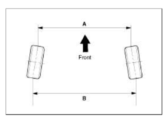
Ð’ - A > 0: Toe in (+)
Ð’ - A < 0: Toe out (-)
Toe adjustment
1. Loosen the tie rod end lock nut.
2. Remove the bellows clip to prevent the bellows from being twisted.
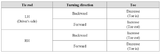
3. Adjust the toe by screwing or unscrewing the tie rod. Toe adjustment should be made by turning the right and left tie rods by the same amount.
Toe
Total: 0º+-0.2º
Individual: 0º+-0.1º
4. When completing the toe adjustment, install the bellows clip and tighten the tie rod end lock nut to specified torque.
Tightening torque : 49.0 ~ 53.9N.m (5.0 ~ 5.5kgf.m, 36.2 ~ 39.8lb-ft)
Camber and Caster
Camber and Caster are pre-set at the factory, so they do not need to be adjusted. If the camber and caster are not within the standard value, replace or repair the damaged parts and then inspect again.
Camber angle : -0.5º+-0.5º
Caster angle : 4.02 º +- 0.5º
Rear Wheel Alignment
CAUTION
When using a commercially available computerized wheel alignment equipment to inspect the rear wheel alignment, always position the vehicle on a level surface.
Prior to inspection, make sure that the rear suspension system is in normal operating condition and that the tires are inflated to the specified pressure.
Toe
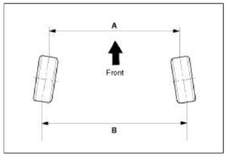
Ð’ - A > 0: Toe in (+)
Ð’ - A < 0: Toe out (-)
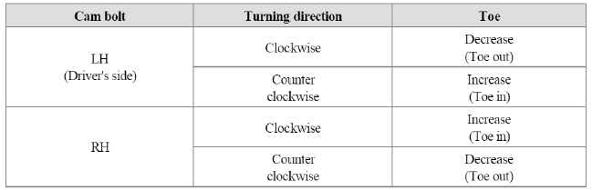
Toe adjustment
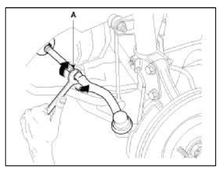
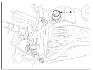
1. Loosen the nut holding the assist arm cam bolt (A).
2. Adjust rear toe by turning the rear assist arm cam bolt (A) clockwise or counter clockwise. Toe adjustment should be made by turning the right and left cam bolt by the same amount.
Toe
Total: 0.2º+-0.2º
Individual: 0.1º+-0.1º
3. When completing the toe adjustment, tighten the nut to specified torque.
Tightening torque: 107.9 ~ 117.7N.m (11.0 ~ 12.0kgf.m, 79.6 ~ 86.8lb-ft)
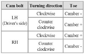
Camber
Adjust the camber by turning the cambolt of the rear lower arm.
Camber: -1.0º+-0.5º
READ NEXT:
 Components and Components Location, Description and Operation
Components and Components Location
Components Location
Receiver
TPMS Sensor
TPMS Sensor
TPMS Sensor
TPMS Sensor
Description and Operation
Description
TREAD Lamp
Tir
TPMS Sensor
Description and Operation
Description
1. Mode
Configuration State
All sensors should be in the Low Line (Base) state.
In Low Line (Base) configuration, sensor transmissions occur e
SEE MORE:
Heated steering wheel
When the ignition switch or ENGINE
START/STOP button is in the ON position,
pressing the heated steering wheel
button warms the steering wheel. The
indicator on the button will illuminate.
To turn the heated steering wheel off,
press the button once again. The indicator
on the button will
Operating HomeLink
Operating HomeLink
1) Operating HomeLink
Press and release the desired programmed
HomeLink button (1, 2 or 3).
NOTICE
The HomeLink indicator (7) should light
green, solid or flashing, and your programmed
device should operate.
If your device does not operate, the
HomeLink prog
Content
- Home
- Kia Sportage - Fifth generation (NQ5) - (2022-2026) - Owner's Manual
- Kia Sportage - Second generation (JEKM) (2005-2015) - Body Workshop Manual
- Kia Sportage Third generation (SL) - (2011-2016) - Service and Repair Manual
- Sitemap
- Top articles
