Kia Sportage: Battery
Description and Operation
Description
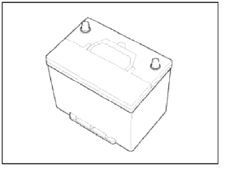
1. The maintenance-free battery is, as the name implies, totally maintenance free and has no removable battery cell caps.
2. Water never needs to be added to the maintenance-free battery.
3. The battery is completely sealed, except for small vent holes in the cover.
NOTE
After disconnecting then reconnecting the battery negative cable, reset some parts that require the reset procedures. (Refer to BE group - General Information)
Components and Components Location
Components
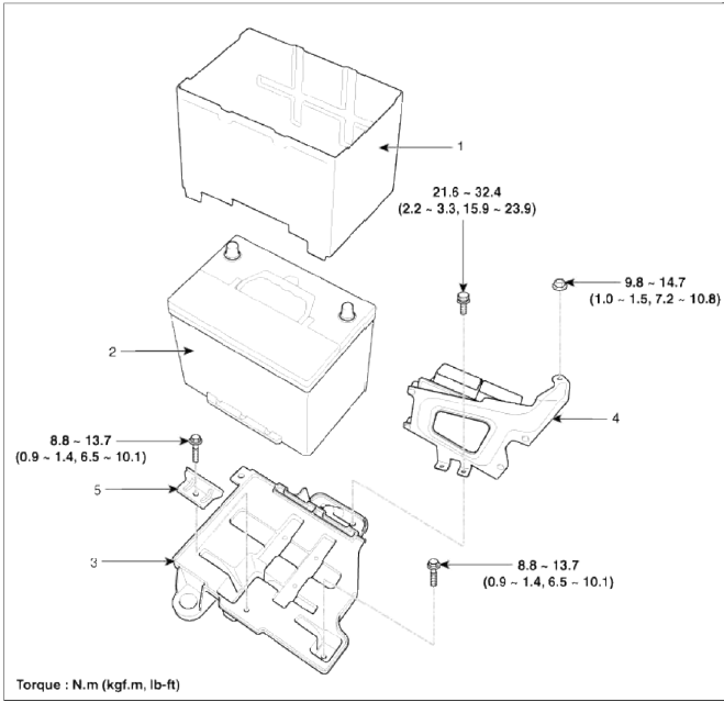
- Battery insulation pad
- Battery
- Battery tray
- ECM & bracket assembly
- Battery mounting bracket
Repair procedures
Removal and Installation
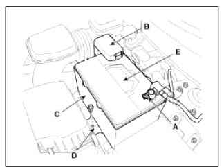
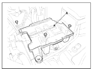
1. Remove the battery.
- Disconnect the battery negative terminal (A)
Tightening torque: 4.0 ~ 6.0N.m (0.4 ~ 0.6kgf.m, 3.0 ~ 4.4lb-ft)
- Disconnect the battery positive terminal (B).
Tightening torque: 7.8 ~ 9.8 N.m (0.8 ~ 1.0 kgf.m, 5.8 ~ 7.2 lb-ft)
- Remove the battery insulation pad (C).
- Remove the battery mounting bracket (D), and the battery (E).
Tightening torque: Bracket bolt: 8.8 ~ 13.7 N.m (0.9 ~ 1.4 kgf.m, 6.5 ~ 10.1 lb-ft)
2. Remove the air duct and air cleaner assembly. (Refer to EM group).
3. Remove the ECM (A) after disconnecting the connectors (B). (Refer to FL group
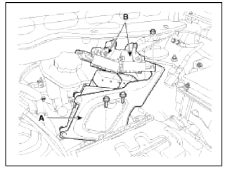
4. Remove the battery tray (A).
Tightening torque: 8.8 ~ 13.7 N.m (0.9 ~ 1.4 kgf.m, 6.5 ~ 10.1 lb-ft)
5. Installation is the reverse order of removal.
CAUTION
When installing the battery, fix the mounting bracket on the tray correctly.
Inspection
Battery Diagnostic Flow
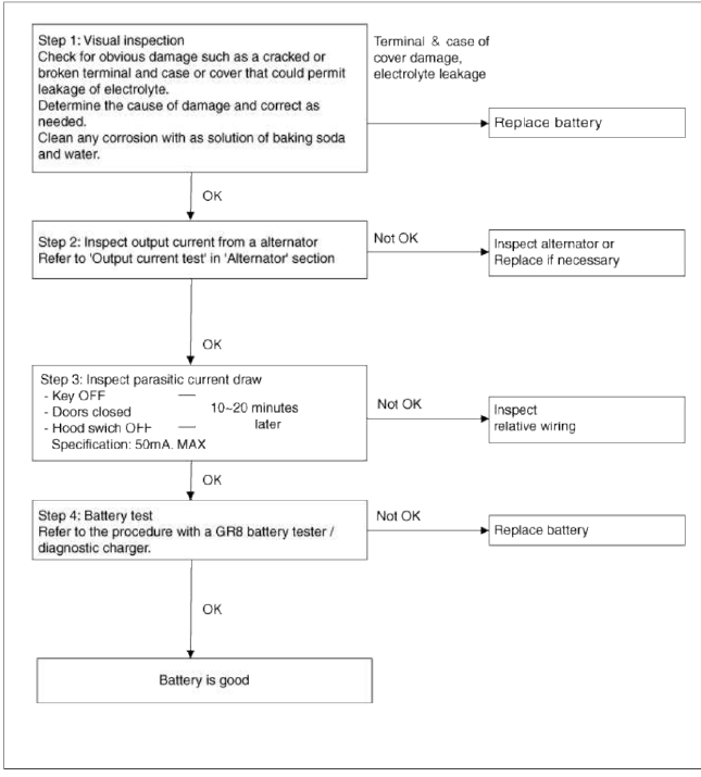
Vehicle parasitic current inspection
1. Turn the all electric devices OFF, and then turn the ignition switch OFF.
2. Close all doors except the engine hood, and then lock all doors.
- Disconnect the hood switch connector.
- Close the trunk lid.
- Close the doors or remove the door switches.
3. Wait a few minutes until the vehicle's electrical systems go to sleep mode.
NOTE
For an accurate measurement of a vehicle parasitic current, all electrical systems should go to sleep mode.
(It takes at least one how or at most one day.) However, an approximate vehicle parasitic current can be measured after 10-20 minutes.
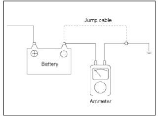
4. Connect an ammeter in series between the battery (-) terminal and the ground cable, and then disconnect the clamp from the battery (-) terminal slowly.
CAUTION
Be careful that the lead wires of an ammeter do not come off from the battery (-) terminal and the ground cable to prevent the battery from being reset. In case the battery is reset, connect the battery cable again, and then start the engine or turn the ignition switch ON for more than 10 sec. Repeat the procedure from No. 1.
To prevent the battery from being reset during the inspection,
- Connect a jump cable between the battery (-) terminal and the ground cable.
- Disconnect the ground cable from the battery (-) terminal.
- Connect an ammeter between the battery (-) terminal and the ground cable.
- After disconnecting the jump cable, read the current value of the ammeter.
5. Read the current value of the ammeter.
- If the parasitic current is over the limit value, search for abnormal circuit by removing a fuse one by one and checking the parasitic current.
- Check the parasitic current again, and search for suspected writ by removing a unit connected with the abnormal circuit one by one.
Limit value (after 10-20 min.) : Below 50mA
Cleaning
1. Make sure the ignition switch and all accessories are in the OFF position.
2. Disconnect the battery cables (negative first).
3. Remove the battery from the vehicle.
CAUTION
Care should be taken in the event the battery case is cracked or leaking, to protect your skin from the electrolyte.
Heavy rubber gloves (not the household type) should be wore when removing the battery.
4. Inspect the battery tray for damage caused by the loss of electrolyte. If acid damage is present, it will be necessary to clean the area with a solution of clean warm water and baking soda. Scrub the area with a stiff brush and wipe off with a cloth moistened with baking soda and water.
5. Clean the top of the battery with the same solution as described above.
6. Inspect the battery case and cover for cracks. If cracks are present, the battery must be replaced.
7. Clean the battery posts with a suitable battery post tool.
8. Clean the inside surface of the terminal clamps with a suitable battery cleaning tool. Replace damaged or frayed cables and broken terminal clamps.
9. Install the battery in the vehicle.
10. Connect the cable terminals to the battery post, making sure tops of the terminals are flush with the tops of the posts.
11. Tighten the terminal nuts securely.
12. Coat all connections with light mineral grease after tightening.
CAUTION
When batteries are being charged, an explosive gas forms beneath the cover of each cell. Do not smoke near batteries being charged or which have recently been charged. Do not break live circuit at the terminals of batteries being charged.
A spark will occur when the circuit is broken. Keep open flames away from battery.
READ NEXT:
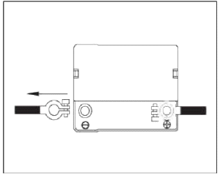
 Battery Sensor
Description and Operation
Description
Vehicles have many control units that use more electricity. These units
control their own system based on information
from diverse sensors. It is impor
Description and Operation | Repair procedures
Description
The starting system includes the battery, starter, solenoid switch, ignition switch, inhibitor switch (A/T), clutch pedal switch (M/T), ignition lock switch, connection wires and t
SEE MORE:
Side Body | Interior
Body Repair
Side Body A
* These dimensions indicated in this figure are actual-measurement dimensions.
Side Body Ð’
* These dimensions indicated in this figure are actual-measurement dimensions.
Interior
Body Repair
Interior A
* These dimensions indic
Ignition System
Description and Operation
Description
Ignition timing is controlled by the electronic control ignition timing
system. The standard reference ignition timing
data for the engine operating conditions are preprogrammed in the memory of the
ECM (Engine Control Module).
The engine operati
Content
- Home
- Kia Sportage - Fifth generation (NQ5) - (2022-2026) - Owner's Manual
- Kia Sportage - Second generation (JEKM) (2005-2015) - Body Workshop Manual
- Kia Sportage Third generation (SL) - (2011-2016) - Service and Repair Manual
- Sitemap
- Top articles
