Kia Sportage: Battery Sensor
Description and Operation
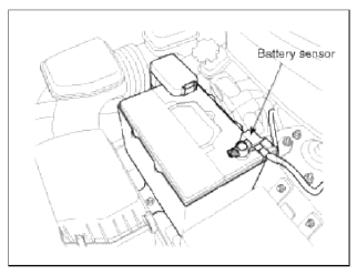
Description
Vehicles have many control units that use more electricity. These units control their own system based on information from diverse sensors. It is important to have a stable power supply as there diverse sensors giving a variety of information. Battery sensor is mounted on battery (-) terminal. It transmits battery voltage, current, temperature information to ECM. ECM controls generating voltage by duty cycle based on these signals.
CAUTION
When battery sensor signal fault occurs, inspect the vehicle parasitic draw in advance after inspecting the sensor because the sensor will behave abnormally when the parasitic draw is more than 100mA. (Refer to vehicle parasitic current inspection)
NOTE
Perform the following process after replacing the battery sensor.
1. Ignition switch ON/OFF.
2. Park the vehicle about 4 hours.
3. After 4 hours later, check the SOC (State of charge) of battery using GDS.
CAUTION
For the vehicle equipped with a battery sensor, be careful not to damage the battery sensor when the battery is replaced or recharged.
1. When replacing the battery, it should be same one (type, capacity and brand) that is originally installed on your vehicle. If a battery of a different type is replaced, the battery sensor may recognize the battery to be abnormal.
2. When installing the ground cable on the negative post of battery, tighten the clamp with specified torque of 4.0~6.0N.m (0.4~0.6kgf.m, 3.0~4.4lb-ft). An excessive tightening torque can damage the PCB internal circuit and the battery terminal.
3. When recharging the battery, ground the negative terminal of the booster battery to the vehicle body. If the negative cable from a battery charger is connected to the negative terminal of the battery, the battery sensor can make an error. In this case, repeat the above process for battery sensor replacement (1~3) after disconnecting and reconnecting the battery connector.
READ NEXT:
 Description and Operation | Repair procedures
Description
The starting system includes the battery, starter, solenoid switch, ignition switch, inhibitor switch (A/T), clutch pedal switch (M/T), ignition lock switch, connection wires and t
SEE MORE:
Battery recharging
Your vehicle has a maintenance-free,
calcium-based battery.
If the battery becomes discharged in a
short time (because, for example, the
headlamps or interior lights were left
on while the vehicle was not in use),
recharge it by slow charging (trickle)
for 10 hours.
If the battery g
Electrical Equipment (U.S. only)
The electrical system of your vehicle is
designed to perform under all reasonably
expected operating conditions.
However, before any additional electrical
equipment is installed in your vehicle,
consult an Authorized Kia Dealer, in
order to ensure that you do not void
your warranty.
Cert
Content
- Home
- Kia Sportage - Fifth generation (NQ5) - (2022-2026) - Owner's Manual
- Kia Sportage - Second generation (JEKM) (2005-2015) - Body Workshop Manual
- Kia Sportage Third generation (SL) - (2011-2016) - Service and Repair Manual
- Sitemap
- Top articles
