Kia Sportage: Description and Operation | Repair procedures
Description
The starting system includes the battery, starter, solenoid switch, ignition switch, inhibitor switch (A/T), clutch pedal switch (M/T), ignition lock switch, connection wires and the battery cable.
When the ignition key is turned to the start position, current flows and energizes the starter motor's solenoid coil.
The solenoid plunger and clutch shift lever are activated, and the clutch pinion engages the ring gear.
The contacts close and the starter motor cranks. In order to prevent damage caused by excessive rotation of the starter armature when the engine starts, the clutch pinion gear overruns.
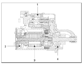
- Solenoid
- Brush assembly
- Armature
- Overrun clutch
Repair procedures
Starter Circuit Troubleshooting
NOTE
The battery must be in good condition and fully charged.
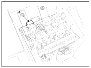
1. Disconnect the fuel pump relay (A) in the fuse box.
2. With the shift lever in N or P (A/T) or clutch pedal pressed (M/T), turn the ignition switch to "START".
If the starter normally cranks the engine, starting system is OK. If the starter will not crank the engine at all, go to next step.
If it won't disengage from the ring gear when you release key, check for the following until you find the cause.
- Solenoid plunger and switch malfunction.
- Dirty pinion gear or damaged overrunning clutch.
3. Check the battery condition. Check electrical connections at the battery, battery negative cable connected to the body, engine ground cables, and the starter for looseness and corrosion. Then try starting the engine again.
If the starter cranks normally the engine, repairing the loose connection repair ed the problem. The starting system is now OK.
If the starter still does not crank the engine, go to next step.
4. Disconnect the connector from the S-terminal of solenoid. Connect a jumper wire from the B-terminal of solenoid to the S-terminal of solenoid.
If the starter cranks the engine, go to next step.
If the starter still does not crank the engine, remove the starter, and repair or replace as necessary.
5. Check the following items in the order listed until you find the open circuit.
- Check the wire and connectors between the driver's under-dash fuse/relay box and the ignition switch, and between the driver's under-dash fuse/relay box and the starter.
- Check the ignition switch (Refer to BE group - Ignition System)
- Check the transaxle range switch connector or ignition lock switch connector.
- Inspect the starter relay.
Starter Solenoid Test
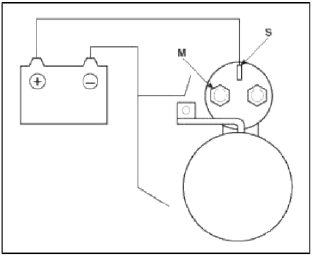
1. Disconnect the field coil wire from the М-terminal of solenoid switch.
2. Connect the battery as shown. If the starter pinion pops out, it is working properly. To avoid damaging the starter, do not leave the battery connected for more than 10 seconds.
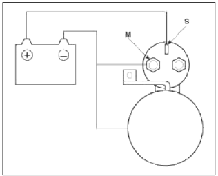
3. Disconnect the battery from the М-terminal.
If the pinion does not retract, the hold-in coil is working properly. To avoid damaging the starter, do not leave the battery connected for more than 10 seconds.
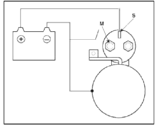
4. Disconnect the battery also from the body. If the pinion retracts immediately, it is working properly. To avoid damaging the starter, do not leave the battery connected for more than 10 seconds.
Free Running Test
1. Place the starter motor in a vise equipped with soft jaws and connect a fully-charged 12-volt battery to starter motor as follows.
2. Connect a test ammeter (150-ampere scale) and carbon pile rheostats as shown in the illustration.
3. Connect a voltmeter (15-volt scale) across starter motor.
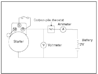
4. Rotate carbon pile to the off position.
5. Connect the battery cable from battery's negative post to the starter motor body.
6. Adjust until battery voltage shown on the voltmeter reads 11.5volts.
7. Confirm that the maximum amperage is within the specifications and that the starter motor turns smoothly and freely.
Current: 105A, MAX
Speed: 2,950 rpm, MIN
READ NEXT:
 Starter
Components and Components Location
Components
Front housing
Starter solenoid assembly
Lever
Lever packing
Planet shaft assembly
Planetary gear assembly
Packing
Shield
Amat
Starter Relay
Repair procedures
Inspection
1. Remove the fuse box cover.
2. Remove the starter relay (A).
3. Using an ohmmeter, check that there is continuity between each terminal.
4. Apply 12V to termi
SEE MORE:
Bulb replacement precaution
Light bulbs are installed in various parts
of the vehicle to provide lighting inside
and outside the vehicle as well as to alert
other vehicles.
Bulb replacement precaution
Please keep extra bulbs on hand with
appropriate wattage ratings in case of
emergencies.
Refer to "Bulb wattage&
Engine Control Module (ECM)
Schematic Diagrams
ECM Terminal And Input/Output signal
ECM Terminal Function
Connector [CHTG-AG]
Connector [CHTG-BG]
ECM Terminal Input/Output signal
Connector [CHTG-AG]
Connector [CHTG-BG]
Circuit Diagram
Repair procedures
Removal
CA
Content
- Home
- Kia Sportage - Fifth generation (NQ5) - (2022-2026) - Owner's Manual
- Kia Sportage - Second generation (JEKM) (2005-2015) - Body Workshop Manual
- Kia Sportage Third generation (SL) - (2011-2016) - Service and Repair Manual
- Sitemap
- Top articles
